

| You are here: Home » Products » PolyTrans|CAD+DCC » 3D File Formats |
Support: 905-672-9328 Copyright © 2024 Okino Toronto, Ontario, Canada. |
The "perspective matching" plug-in system for NuGraf allows a 3D computer generated model to be "overlaid" on top of a real photograph to make the two align together. The alignment is done by iteratively changing the parameters of a 3D computer graphics camera until certain 2D-to-3D constraints are met.
The algorithm takes a photographed bitmap background image and 5 or more "point pair" locators. After the point pairs are set up, and the algorithm run, the outcome is a new or modified virtual camera that is in the approximate same virtual 3D location and orientation as the original (real world) camera from which the photograph was shot.
NOTE: This perspective matching algorithm does not perform motion tracking, where the camera changes location and orientation over time. Instead, it is designed to work with static non-animated background images.
Once the virtual camera has been computed to be in the same location and orientation as the real-world camera, you can place 3D objects in front of the virtual camera and render the scene over top of the photographed background image. The foreground rendered objects will composite over top of the bitmap image and they will appear as if they actually sit inside the photographed scene! This is shown in the following images:

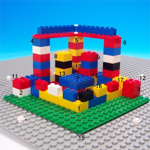
Click on images to view full resolution renditionsIn the images above, the left bitmap is a photograph of a real LEGO setup. In the middle image, we've marked locations on the photograph where we have taken measurements of where the bricks were located in the "real world" relative to the camera location; we have chosen 17 locations to use as the 2D-to-3D point correspondences since a good number of points are needed to make the final camera orientation numerically accurate (the low resolution 512x512 background image does not offer super high accuracy). In the right image, we've created some 3D computer graphics bricks (blue, white and yellow), one LEGO man and 2 flags, of a relative scale and location comparable to the original real-world scene. Once the perspective match algorithm has been set up with the 2D-to-3D point correspondences, the algorithm is run and it aligns the final computer graphics camera to be approximately in the same location and FOV as the original real-world camera. When the new LEGO bricks, LEGO man and flags are rendered over top of the photographed background image, they appear to be as one.

The camera perspective matching dialog box can be accessed by one of the following methods:
- Left-click the vertical "Cameras" tab on the selector window, click and hold the mouse button down in the list box area then choose the "Perspective Match" menu item.
- Click and hold the RIGHT mouse button down over the vertical "Cameras" tab on the selector window and choose the " Perspective Match" menu item.
- Assign a photographed bitmap image as the background for the rendered scene. This is done by accessing the Background Options dialog box (main menu "Options/Background Options
") and selecting the bitmap via the "
Bitmap" panel.
- Press the icon located in the upper-left corner of the camera view window (the upper-right view window) and deselect the "Display Attributes/Grid Visible" menu option. You do not want to have the 3D grid enabled during perspective matching.
- Press the icon located in the upper-left corner of the camera view window (the upper-right view window) and select any of the OpenGL display modes, such as the "Display Mode/OpenGL: Smooth Shaded".
- Press the icon located in the upper-left corner of the camera view window (the upper-right view window) and select the "
Configure OpenGL Options
" menu item. Press the "Background" panel tab, enable the "Enable background image" checkbox and enable the "Use the same background bitmap image and options as used by the NuGraf renderer" checkbox. Press the OK button. This will cause your photographed bitmap image to appear behind the camera view window.
- Constrain or set the renderer's X and Y image resolution's aspect ratio equal to the aspect ratio of the background image. This can be done on the Runtime Options dialog box (press Control-O) and set the "Image Aspect Ratio" combo box to "Same as Background Image". This will ensure that the final rendered image will have the same aspect ratio as the background image.
- If you have the camera view window zoomed up, un-zoom it so that all 4 view windows are seen.
- Start the "Perspective Match" dialog box. See above for the 2 methods to access this dialog box.
- If you wish to reset the dialog box to power-up defaults, or to delete any point-pairs from a previous session, press the "
Reset" button.
- Assign 5 or more 3D-2D "point pairs" markers (see below for an explanation). This can be done interactively with the mouse or by pressing the "Add new pair" button 5 or more times, then editing the 3D and 2D point values via the type-in edit controls.
- Once you are sure that all point-pairs have been set up accurately, press the "Modify Current Camera" button. The perspective match algorithm will compute a solution and move the virtual 3D camera to the approximate same location as the original real-world camera which photographed the scene. If you wish to create a new camera and not modify the existing camera then press the "Add New Camera" button instead.
- Render the scene using the NuGraf renderer. Your virtual 3D objects should appear composited over top of the background photograph image, and in the same perspective as that of the original real-world camera.
- If the camera location is not correct, or the "Error, last pass" value is very high (say, over 1 or 2), then adjust the point-pair markers and press the "Modify Current Camera" or "Add New Camera" buttons again. Iterate until you achieve a good solution.
The success of the perspective match algorithm depends heavily on the proper and precise location of "point-pair" markers in the orthographic and camera view windows.
First of all,
- On the upper-right camera view window, which has the photographed bitmap image behind it, identity at least 5 or more distinct locations throughout the 3D photographed scene that you wish to use. The locations cannot be all in the same line. It is best to distribute these points throughout the image.
- In the front, top and right orthographic view windows you need to identify the 3D world-space locations which correspond to each feature pinpointed in the photograph image as shown in the perspective camera view. The 5 locations cannot be in the same plane or else the perspective matching algorithm will not work. For example, if the photograph is a picture of a downtown city block and you wish to place a new skyscraper building into the photograph, you would build a 3D model of the skyscraper and surrounding city block, to absolute scale, in the 3D orthographic view windows. The 5 or more 3D markers could be the 4 corners of the city block (which you may have physically measured) and several points on the virtual 3D building. The relative scale of the objects in the virtual 3D scene must be exactly the same as the relative scale of the reference objects in the photograph (ie: the city block).
Now, you need to set up the point-pair markers via the perspective match dialog box:
- Press the "Add new pair" button 5 or more times to add 5 or more entries to the "Point-Pair Names" list box. Click on the first entry in the list box. Alternatively, you can enable the "Add 3D Point at Cursor" radio button, press and hold down the CTRL key on the keyboard, and click in any orthographic view window; every time you click the mouse down a new 3D marker will be created as long as you keep the CTRL key depressed. To move these markets in the orthographic view windows select the "Place 2D or 3D Point at Cursor" radio button and click the mouse in the ortho view windows.
- In the 3 orthographic view windows click the mouse down to set the 3D point-pair marker location of the red X icon with a square around. Click at the location of one of your pre-chosen reference markers in the 3D scene. Likewise, click the mouse in the upper-right camera view window to set the 2D point-pair marker location on the photograph, which is shown as a red circle with a "+" in the middle. This defines one "point pair" marker combination. For example, with the city block example, place one X icon at one corner of the virtual 3D building and the + icon over the photograph where that portion of the 3D building is to sit.
- Alternatively, you can highlight one of the pair-pair names in the list box and set the location of the 2D and 3D points using the type-in edit controls on the dialog box. Press the Enter key to have the dialog box accept the new values.
- Repeat this process by clicking on the next entry in the list box so that it comes highlighted, and set the location of the red X marker in the ortho view windows and the red + marker in the camera view window.
- You need to obtain accurate measurements of specific feature locations in your photographed scene. The 3D marker locations must be set up in the orthographic view windows in the same relative locations as measured from the real world scene.
- To start, you should place your virtual 3D camera in the approximate same location that you believe the real-world camera was located. At least the same quadrant of space and viewing angle will aid in the perspective matching algorithm to compute the proper location.
- All parameters and point-pairs will be saved to a .ini file between invocations of the NuGraf software. Thus, you can exit the software, come back in, and find that the perspective match setup is the same as last time.
- Likewise. all parameters and point-pairs will be saved to the Okino .bdf file format between invocations of the NuGraf software. Thus, the next time you load up that .bdf file you will find that the perspective match setup is the same as last time the .bdf file was saved. These parameters override the values saved to the .ini setup file.
- For the algorithm to work adequately, the 3D marker locations cannot all lie in a single plane, and the 2D marker locations cannot all lie on a straight line.
This lists all of the point-pair markers currently defined. To select another point-pair for editing click on its name in this list box.Add New Pair Button
This adds a new default point-pair to the list box. The 2D marker will be located in the center of the camera view window. The 3D marker will take its initial value from the "Numeric Entry of 3D Points" type-in boxes.On/Off Radio Buttons
This will cause a point-pair to be enabled or disabled. If it becomes disabled (gray color) then it will not be used in the perspective matching algorithm. To change the on/off state, select one of the point-pairs using the list box then change the radio buttons.Delete, Delete All
These buttons will delete the currently highlighted point-pair, or all point-pairs. You can also press the Reset button to delete all point-pairs.Rename Point-Pair
If you wish to rename the currently highlighted point-pair in the list box, type in the new name here and press the Enter key.Display Colors
These three swatches define the colors for the selected, non-selected and disabled marker icons (respectively) shown on the view windows. You may need to change their colors in case the bitmap image uses the same colors as the marker icons and they blend together. Click on any color swatch to change its color.Numeric Entry of 3D Points
If you wish to specify the location of the 3D marker numerically, highlight one point-pair in the list box and type in its new 3D location using these edit boxes. Press the Enter key to have the new values accepted.Numeric Entry of 2D X-Y Point on Perspective Window
If you wish to specify the location of the 2D marker numerically, highlight one point-pair in the list box and type in its new 2D location using these edit boxes. Press the Enter key to have the new values accepted. The 2D location is measured in pixels.Add 3D Point at Cursor, radio button
This places the mouse into the add-new-3D point cursor mode. When this radio button is enabled then you can click the mouse in any orthographic view window (top, front, right) and a new 3D marker will be created at that absolute location where you clicked the mouse. After you click the mouse on the view window it will change into the "Place 2D or 3D Point at Cursor" mouse mode so that you can tweak the location of the new 3D marker location. If you would rather continue adding 3D points instead then press and hold down the CTRL key.Place 2D or 3D Point at Cursor, radio button
This places the mouse into the place 2D or 3D point cursor mode. When this radio button is enabled then you can click the mouse in any orthographic view window (top, front, right) to move the location of the current 3D marker location. If you click in the perspective camera view window then the current 2D marker location will be moved to that cursor location.Camera View Computation Controls
Once the 5 or more active point-pair markers are specified, the following controls will be available to compute the final solution.Modify Current Camera, Add New Camera
Press either of these buttons to have the perspective matching algorithm invoked and to have the virtual 3D camera moved and orientated to be in the same location and orientation as the real-world camera which photographed the scene. The "Modify" button will modify the location and orientation of the current camera while the "Add New" button will add a new camera to the scene and make it the active camera.Do Not Change Field of View
If this checkbox is enabled (check marked) then the perspective match algorithm will not modify the current camera's field of view. You might want to set this checkbox if you have already set up the field of view of the virtual 3D camera to be the same as the measured field of view of the real-world camera.Numer of Iterations
This type-in box defines the maximum number of iterations of the perspective match algorithm that will be computed before stopping. The default is 500 which should be more than ample.Error, Last Pass
This text lists the root-mean-square (RMS) error of the final iteration of the perspective match algorithm. Smaller numbers (near 0) result in more accurate solutions.