

| You are here: Home » Specialized Sections |
Support: 905-672-9328 Copyright © 2024 Okino Toronto, Ontario, Canada. |

Hints and Tips for Using the Polygon Reduction Algorithm
![]()
![]()
![]()
See also:
§ Save your scene and model data to disk before applying the polygon reduction algorithm. Depending on which options you select for the "New object creation method" dialog box option you will not be able to revert to the old objects again. The Okino .bdf file format is the most ideal file format to save your scene and model data to disk.
§ You can Undo the operation by pressing Control-Z if the "New object creation method" combo box is not set to "Replacing existing object".
§ You can apply polygon reduction during the Batch 3D Conversion process by enabling the "Perform Polygon Reduction on Each Model" option on the batch 3d conversion options dialog box.
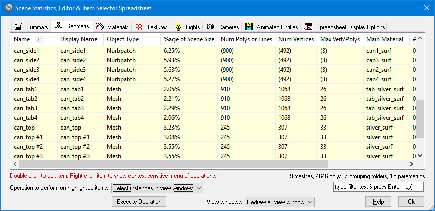
§ You can apply polygon reduction on one of more highlighted instances via the spreadsheet editor (Control-E from the keyboard), "Geometry" panel, "Polygon reduction" combo box operation.
§ Let's assume you have set the "New object creation method" combo box to the "Add new object, hide original object" mode and reduced a scene into a number of new reduced objects, with the old objects hidden. What operations can be performed to delete the set of newly reduced objects and un-hide the original unreduced objects? The operations are:
§ Select the "Delete Un-Hidden Instances" menu item accessible via multiple menus in the software. This will delete the newly reduced objects (as well as all other un-hidden geometry).
§ Select "Unhide All Instances" menu item accessible via multiple menus in the software. This will unhide the original unreduced geometry.
§ To perform polygon reduction on every object in the scene, right click on the "world" green folder (shown in the Selector Window) and click on the "Polygon reduction" menu item. Alternatively select the "Geometry/Polygon reduction/Apply to all objects in scene" main menu item.
§ To perform polygon reduction only on the children of a "yellow folder" (empty instance grouping node), or of the children of a "red folder" (empty object grouping node), do one of the following:
1. Right click on the yellow folder and select "polygon reduction", or
2. Right click on the turquoise icon (the instance of the red folder) above a red folder and select "polygon reduction", or
3. Left click on the yellow folder so that it and its children become selected, then click the "Geometry/Polygon reduction/Apply to selected instances only" main menu item, or
4. Left click on the turquoise icon (the instance of the red folder) above a red folder so that it and its children become selected, then click the "Geometry/Polygon reduction/Apply to selected instances only" main menu item.
§ If a model consists of a closed surface (such as a car body), but the body is broken into multiple objects, then wide cracks may appear between abutting surfaces after the reduction algorithm has finished. This is because each object is reduced irrespective of the other abutting objects. To solve this problem select all the objects that should belong together and select the "Move selected objects to new object" command under the Geometry main menu. This will move all objects into a new single object and weld their vertices together so that it will ideally act as one continuous meshed surface. This resulting "uni-body" will most likely provide much better polygon reduction results. Alternatively, increase the "Boundary preservation weight" type-in value shown on the "Weightings" panel or enable the "Lock the vertex positions of vertices on mesh borders" checkbox on the same panel.
§ Quick ideas to control boundary vertex placement (see this tutorial):
1. If you don't want boundary (outer edge) vertices to move at all, enable the
§ Lock the vertex positions of vertices on mesh borders
2. Or, if you don't want the shape of the boundary (outer edge) to change but you will allow these vertices to shift around a bit, then set the
§ "Boundary preservation weight" to a high number like '1e6'.
3. If you don't want material boundary vertices to move at all, enable the
§ Lock the vertex positions bordering two materials
4. Or, if you don't want the material characteristics of the object to change very much but you will allow these coordinates to shift around a bit, then set the
§ "Material preservation weight" to a high number like '1e6'.
§ If you find that reducing an entire model at the same time produces non-optimal results, then try performing the polygon reduction only on selected sub-sets of the models using different parameters and different reduction amounts.
§ The polygon reduction algorithm works optimally if you try to achieve the following three points:
1 The meshes should be "closed manifold surfaces". Essentially this means that all abutting polygons share the same edge and same vertices. If the model is cleanly built, and abutting polygons have overlapping vertices, then this should not be a problem. However, it is often a problem with tessellated NURBS patches from CAD programs for which abutting polygons do not necessarily have shared vertices (for example, a long edge of a large triangle might have its edge abutted with 20 small triangles; where the vertices meet are called "T vertices" because the edges of the small triangles meet at a 'T" with the long and large triangle edge). In these cases gaps will show in the final reduced object because there was no vertex connectivity along these "T" vertex edges.
2. The algorithm best works with medium sized coherent objects, say in the approximate 10,000 polygon size per object. If you have lots of very small objects (few polygons) then a high level of polygon reduction, applied to each small object individually, will lead to low quality and excessive reduction. On the other hand, applying the reduction algorithm to only a few objects with many polygons (100,000) will lead to slow reduction results and most probably memory overrun. Thus, there is a happy medium somewhere between these two extents. The online polygon reduction tutorials cover the issues involved with reducing one object or reducing all objects at once.