

| You are here: Home » Specialized Sections |
Support: 905-672-9328 Copyright © 2024 Okino Toronto, Ontario, Canada. |

Dialog Box Option Descriptions
![]()
![]()
![]()
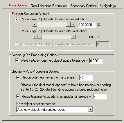
Polygon Reduction Amount
One of the two main methods to control the degree of polygon reduction is with either of these two mutually complementary sliders. The top slider specifies the percentage of the original model you wish the polygon reduction algorithm to remove. The default is 80% (the reduction algorithm may not actually remove this percentage of the model exactly due to vertex constraints on the model).
As the top slider is increased the bottom slider is decreased. The bottom slider is the percentage of the model to keep after reduction is complete. It is simply the inverse of the top slider. Changing one slider inversely changes the other slider.
The other main method to specify the degree of polygon reduction is via the " Geometric Error Tolerance" type-in parameter. This is described below and in the Geometric Error Tolerance Reduction Method tutorial.
NOTE: The sliders will specify the amount of reduction to apply to each object individually. Thus, if you have 100 objects in your scene then each will reduced independently of each other until each model attains the desired amount of reduction. In many cases this will causes some parts to become over-reduced and other parts to become under-reduced. To evenly distribute the amount of reduction evenly across all 100 objects, please refer to the Geometric Error Tolerance Reduction Method tutorial.
Geometry Pre-Processing Options
The following geometry processing is applied to the objects prior to sending them to the polygon reduction algorithm.
Weld vertices together, object space tolerance = #
It is imperative in the polygon reduction algorithm that all adjacent and touching polygons share the same vertex coordinates. If a mesh does not use shared vertices amongst its polygons then the polygon reduction phase will not consider them to be "one continuous surface" and thus cracks or holes may appear between previously touching polygons.
If this option is enabled, which is the default, then all redundant or duplicated vertices that are close together in space will be "welded" into a unique and single set of vertices, thus insuring that all abutting polygons use shared vertices. If the distance between two vertices is less than the " object space tolerance" type-in value, then the two vertices will be welded into a single vertex prior to the mesh being submitted to the polygon reduction algorithm.
Geometry Post-Processing Options
The following geometry processing is applied to the objects after having had the polygon reduction algorithm applied to them.
Recompute new vertex normals, smoothing angle = #
When the amount of polygon reduction is high (for example, 80%) there is a corresponding large number of polygons that are removed or modified in the object. As a result, the vertex normals of the original object are greatly reduced in numbers. "Vertex normals" are associated with each vertex of each polygon in the object, and they help define the smoothness factor from one polygon to the next. When a large number of vertex normals are removed from an object, the resulting smoothness quality suffers. For example, a corner of a box which may have originally been nicely rounded (approximated by a number of thin polygons to approximate the rounded corner) might end up being a sharp corner due to the removal of all the thin polygons; likewise, the vertex normals which helped define a rounded corner end up (sometimes) in a non-optimal direction. When these new objects are rendered they may appear to have "black spots " or "dark regions" where you would otherwise not expect these rendering anomalies to appear. These are all to be expected from polygon reduction in the case of extreme reduction in the number of polygons.A simple and reliable solution to these vertex normal problems is to enable this " Recompute new vertex normals" check box (enabled by default). This will compute completely new vertex normals for the entire model. The type-in smoothing angle defines the cut off point between sharp corners and smooth corners. If two polygons meet at an angle less than the smoothing angle, then they will end up looking smooth; if the polygons meet at an angle greater than the smoothing angle, then they will end up looking like a sharp corner. The default is 45 degrees. If you set this number lower (such as 20 degrees) then more sharp edges will appear, which is sometimes better for CAD data with a mixture of rounded and sharp edges. If you set the angle to 90 degrees then everything will end up being (over) smoothed. 20 to 45 degrees seems to be a good range to use this parameter.
New object creation method:
This drop-down combo box determines how the newly reduced object is to be re-inserted back into the PolyTrans internal geometry database.
Replace existing object
This will cause the original un-reduced object to be deleted and the newly reduced object to replace the original object. All material assignments, instance attributes and texture projections will be re-assigned to the new object. It will also be attached to the original parent in the hierarchy.Add new object, hide original object
This will add the new reduced object to the scene at the same hierarchy level of the original un-reduced object. The original un-reduced object will be hidden in the scene but not deleted. This is the default option.
If you wish to delete the hidden objects from the scene at any time, select the "Delete Hidden Instances" menu item accessible via multiple menus in the software.
If you wish to delete the newest objects which were just reduced and added to the tree, then revert to the original unreduced original objects: select the "Delete Un-Hidden Instances" menu item accessible via multiple menus in the software and then select "Unhide All Instances" menu item.
Add new object, don't hide original object
This will add the new reduced object to the scene at the same hierarchy level of the original un-reduced object. The original un-reduced object will not be hidden and will not be deleted from the scene. In general this is not a useful option to enable unless you want the un-reduced and reduced objects to both appear in the scene at the same time.
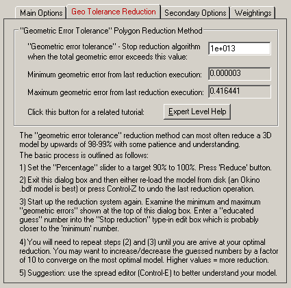
Geometric Error Tolerance
This option is best explained in the "Geometric Error Tolerance" tutorial.
There are two primary methods to stop the amount of reduction of a model: (1) set the maximum percentage of polygons to remove and (2) set the maximum error that is allowed to accumulate for the models.
As a rough example, you would set the reduction slider to 100% and set the "Geometric Error Tolerance" type-in value to 0.001. If you reduce the model you might find that you get 38% reduction. Now, you might increase the type-in value arbitrary to 0.01 and get a reduction amount of 78%. What you are basically doing is telling the reduction algorithm to stop reducing when the total error accumulated reaches some maximum amount. The trick is to find that perfect number whereby the reducer stops and removes the exact percentage of polygons you wish based on the entered " Expert Level Polygon Reduction Amount" type-in value
Higher values will lead to more reduction (since more error is allowed to be accumulated) and lower values will lead to less reduction. Values like 100 to 1 million should, in essence, disable this option from affecting the final polygon reduction amount.
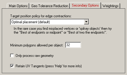
Target position policy for edge contractions
This polygon reduction algorithm reduces the number of polygons in a model by contracting 2 vertices so that multiple polygons collapse to a fewer number of polygons. This is shown in the following diagram for which vertices v1 and v2 are combined to the new vertex position v', thus removing 2 polygons from the mesh:
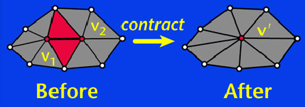
(image Copyright © Michael Garland and Paul S. Heckbert.). The "Target position policy for edge contractions" combo box option determines where the new position of vertex v' will be placed between the original vertex positions v1 and v2.
Optimal placement (default)
The new vertex position v' will be placed anywhere (not necessarily on the line between v1 to v2) such that the resulting geometric error is minimized. As its name implies, the new location is the best new location where the new vertex could be placed to preserve the original appearance of the object. This is the default option.
Best point along edge
The new vertex position v' will be placed along the line between v1 to v2 such that the resulting geometric error is minimized. Not a useful option to enable.
Best of endpoints or midpoint
The new vertex position v' will be placed either at the original vertex locations v1 or v2 (the end points), or at the mid-point between vertices v1 and v2, whichever results in the least geometric error.
Best of two endpoints
The new vertex position v' will be placed either at the original vertex location v1 or at the original vertex location v2. This is the best choice when you wish to have the new reduced mesh be a subset of the original mesh (such that the new mesh shares the same vertices with the old mesh, as when doing adaptive polygon subdivision); no new vertex locations will be generated. The overall fit of the new reduced model will be inferior than if the "Optimal placement" method was used.Minimum polygons allowed per object
This value determines the absolute minimum number of polygons that each object can be reduced down to. For example, if you want to ensure that every object in the scene after reduction has at least 20 polygons, set this value to 20.
Only process raw geometry
If this option is enabled (check marked) then the polygon reduction algorithm will only consider the raw vertex geometry while performing the reduction.Note that enabling this option is semi-equivalent to setting the "Material preservation weight" option to 0.0.
Retain UV tangents
If this checkbox is disabled (un-checkmarked) then any UV tangent vectors associated with the mesh data will be throw away prior to reduction of the mesh. In some cases this will lead to higher quality reductions due to the fewer constraints on each vertex (there will no longer be any UV tangent constraints if this option is disabled). Note: this option will have little or no relevance to anyone using this reduction system.
The following 3 images are prime examples which illustrate when this option should be disabled. The chess pieces on the left all have valid UV tangent vectors, but there is little sharing between the UV tangent coordinates. Thus, when reduced, the extra constraints introduced into the polygon reduction phase cause the mesh to be of low quality, as shown in the second image. If the "Retain UV tangents" option is disabled and the reducer executed on the original mesh again, the third mesh is created which is a much more pleasing reduction.

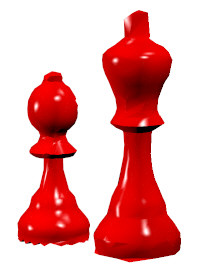

NOTE: UV tangent vectors are only used in a few 3D rendering programs. They are only used when performing texture bump mapping with a bitmap image. The UV tangents at each vertex, along with the vertex normal, create a 3D coordinate system which is used to determine how the vertex normal is to be perturbed (bump mapped). Programs such as 3ds Max, Maya, LightWave and Cinema-4D do not import/export UV tangent vectors and thus disabling this option has little effect on data transferred to/from these named programs. However, Okino's NuGraf software uses these UV tangent vectors for its 2D bump mapping; if you should have these UV tangents discarded via the polygon reduction routine then they can be recreated by assigning a planar, spherical, cylindrical or cubical texture projection icon to each instance (which might be a tedious operation for many objects in a scene).
This panel controls how much the polygon reducer is allowed to move vertices around, or to delete/merge vertices.
Please refer to these tutorials for more real-world examples:
Quick ideas (see this tutorial):
- If you don't want boundary (outer edge) vertices to move at all, enable the Lock the vertex positions of vertices on mesh borders
- Or, if you don't want the shape of the boundary (outer edge) to change but you will allow these vertices to shift around a bit, then set the "Boundary preservation weight" to a high number like '1e6'.
- If you don't want material boundary vertices to move at all, enable the Lock the vertex positions bordering two materials
- Or, if you don't want the material characteristics of the object to change very much but you will allow these coordinates to shift around a bit, then set the "Material preservation weight" to a high number like '1e6'.
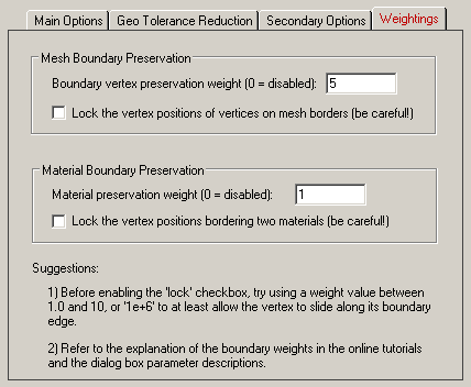
Mesh Boundary Preservation
The basic premise of the polygon reduction algorithm is that it is allowed to move or remove vertices so that multiple polygons can be collapsed into fewer polygons. A side effect of this vertex removal process is that edges that define a boundary of an object can move around, leading to jagged edges at boundaries. The options below help prevent, or reduce, the degree to which boundary vertices are allowed to move in the reduction process.
Boundary preservation weight (0 = disabled)
This type-in value controls how much the polygon reduction algorithm is allowed to move the location of vertices located on the object boundaries. A value of 0 will disable any restrictions and will give complete freedom to the polygon reduction algorithm to move the vertex anywhere. The default value is 5 which will place emphasis on the polygon reducer to keep the vertex somewhere on its boundary edge but not off the edge. Higher values will constrict the vertex so that it remains on its edge (somewhere).
If you want to retain the shape of the border of an object but not lock the vertex locations absolutely (see below) then set this type-in value to "1e6", which is a very high weight. The vertices will still move around (along their edges) but the overall shape of the boundary will not change much.
Tutorial references:
Lock the vertex positions of vertices on mesh borders (Be Careful!)
If this checkbox is enabled (check marked) then boundary vertices will not be allowed to move at all (even along their edges as with the vertex boundary weighting option explained above).
It is recommended that you first try setting the "Boundary preservation weight" to a very high value (such as 1e6) before you try enabling this option. The former weighting option will allow the boundary vertices to move along their edges which will most likely lead to a higher level of polygon reduction than if the "Lock the vertex positions" checkbox is enabled instead.
In extreme cases you will want to enable this option. However, if you enable this with the reduction slider set to a high value (such as 80 or 90%), then the reduced model might appear to be bent out of shape; this is because the borders are locked in space and not much else is allowed to move so extreme movement must be done in order to achieve the desired level of polygon reduction.
Locking the absolute location of vertices can also be useful if a very large mesh is initially broken apart into multiple pieces, simplified individually and stitched back together again. Because the boundary vertices are locked during reduction they will match up once again when pieced back together after reduction.
Material Boundary Preservation
This section of options is very similar to those for the "Mesh Boundary Preservation" described above. However, instead of dealing with the physical boundary of the mesh, these options apply to internal boundaries within a single mesh, boundaries between two or more polygons which have different material attributes.
Material preservation weight (0 = disabled)
This type-in value controls how much the polygon reduction algorithm is allowed to move the location of vertices located between two of more polygons with different material attributes (such as one polygon colored with a red material and another colored with a green material).
A value of 0 will disable any restrictions and will give complete freedom to the polygon reduction algorithm to move the vertex anywhere. The default value is 1 which will place some emphasis on the polygon reducer to keep the vertex somewhere on its material boundary edge but not off the edge. Higher values will constrict the vertex so that it remains on its edge (somewhere). You would have to experiment with different values and see how they affect the final mesh. Try values from 1 to 10 to start off with.
If you want to retain the characteristics of the material border of an object but not lock the vertex locations absolutely (see below) then set this type-in value to "1e6", which is a very high weight. The vertices will still move around (along their edges) but the overall characteristics of the boundary will not change much.
Tutorial references:
Lock the vertex positions bordering two materials (Be Careful!)
If this checkbox is enabled (check marked) then material boundary vertices will not be allowed to move at all (even along their edges as with the vertex boundary weighting option explained above).
It is recommended that you first try setting the "Material preservation weight" to a very high value (such as 1e6) before you try enabling this option. The former weighting option will allow the material boundary vertices to move along their edges which will most likely lead to a higher level of polygon reduction than if the "Lock the vertex positions" checkbox is enabled instead.
In extreme cases you will want to enable this option. However, if you enable this with the reduction slider set to a high value (such as 80 or 90%), then the reduced model might appear to be bent out of shape; this is because the material borders are locked in space and not much else is allowed to move so extreme movement must be done in order to achieve the desired level of polygon reduction.