

| You are here: Home » Products » PolyTrans-for-Maya |
Support: 905-672-9328 Copyright © 2024 Okino Toronto, Ontario, Canada. |
PolyTrans-for-Maya - Import Option Descriptions
PolyTrans-for-Maya - Import Option Descriptions
The most recent documentation for the PolyTrans-for-Maya import options dialog box can be found in the demo version of the software.
The following sections describe the options on the PolyTrans to Maya dialog box. This dialog box controls how the scene geometry is converted from PolyTrans (and its corresponding import converter) to the Maya software:
| Meshes | NURBS | Bitmap Conversion Options |
|---|---|---|
![[Page1]](mayaimpsml2.gif) |
![[Page1]](mayaimpsml3.gif) |
![[Page1]](mayaimpsml1.gif) |
| Enables | Animation |
|---|---|
![[Page1]](mayaimpsml4.gif) |
![[Page1]](mayaimpsml5.gif) |
The import process proceeds as follows:
- The user loads in the PolyTrans-for-Maya plugin module via the plug-ins manager dialog box. This is displayed in Maya through these menu items: Window/General Editors/Plug-In Manager. On this dialog box enable the checkmarks beside the ptio.mll plug-in listing; this it the PolyTrans plug-in module for Maya.
- To display the PolyTrans-for-Maya import/export converter dialog box, type pt in the Maya command line.
- Click on the Import tab located just above the list box containing the import/export converters:
- If you wish to modify the import options prior to starting one of the import converters then press the Import Options button located below the listbox. The PolyTrans to Maya dialog box will appear. These options control how the scene data will be imported into the Maya internal database from the PolyTrans internal database. Press Ok to continue.
- Click on one of the import converters listed in the listbox. A filename selector will appear with which you can choose the filename(s) to import. Note that one or more files can be imported at the same time.
- After the filename selector goes away, the scene data is sent from the PolyTrans internal database to the Maya internal database.
- The corresponding PolyTrans import converter DLL is then loaded and executed. The data will then be imported from the PolyTrans internal database to the Maya database.
This dialog box controls how referenced bitmap files will be handled during the import into Maya.
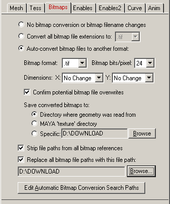
No Bitmap Conversion or Bitmap Filename Changes (Radio Button)
If this radio button is chosen then any bitmap reference imported into Maya will not be changed, its filename extension won't be changed, the path to the bitmap will not be changed and no bitmap conversion will be done.Convert all Bitmap File References To... (Radio Button)
Rather than convert referenced bitmap images to another file format this radio button (when selected) simply changes all the file extensions on bitmap files to a specific type. For example, if set to TIFF then all bitmap filenames imported into the Maya will be changed so that their file extensions end in .tif. This is a useful option is you already have all of the referenced texture maps converted to the desired file format (either from a previous invocation of this import converter or by using a batch bitmap conversion program).Auto-Convert Bitmap Files to Another Format (Radio Button)
If this radio button is selected then all 2d bitmap textures which are currently defined and referenced by the internal NuGraf/PolyTrans database scene will be automatically tagged then converted to a new user-specified 2d bitmap file format. For example, if you are importing a Lightwave scene to Maya, and the Lightwave file references IFF bitmap files then this option can be enabled so that the IFF images get converted to TIFF format automatically.If the bitmap texture(s) cannot be found in the location specified by the pathname prepended to the texture filename then the export converter will search for the texture(s) in all directories specified in the Maya Bitmaps file search paths (these can be modified by choosing the File/Configure Paths dialog box and clicking the Bitmaps tab).
Bitmap File Format (Combo Box)
This combo box lists the destination bitmap file format.Bitmap Bits/Pixel: 2, 4, 8, 24 (Combo Box)
This combo lists determine the number of bits/pixel to write out to the new 2d bitmap file. The default is 24 bits. A color quantization algorithm will be used for the 2, 4 and 8 bits/pixel output formats. Not all bitmap file formats can accept 2-8 bits/pixel (in particular JPEG).Dimensions: X = #, Y = #
These two drop-down list boxes determine the X and Y resolution for the converted bitmap file(s):
No Change = Do not change the X or Y size Closest = Use the next highest power-of-2 size 2, 4, 8, ... 256, 512 = Choose a specific size for the X or Y dimension Confirm Potential Bitmap File Overwrites
If this checkbox is enabled (checkmarked) then the bitmap converter will confirm any potential overwrites of existing bitmap files on disk which have the same filename and extension as the one being written. If this option is disabled then no confirmation will be made.Save Converted Bitmaps To...
These radio buttons determine where the new bitmap file will be written to. Note that enabling the Replace all Bitmap File Paths With This Path: option or the Strip File Paths From All Bitmap References option below will change the path prefix for the converted bitmap even though it was saved to disk in the location specified by one of these 3 radio buttons.Directory Where Geometry Was Read From
The new bitmaps will be written to the directory where the original geometry file(s) were read from.Maya textures Directory
The new bitmaps will be written to the Maya textures directory.Specific + Browse
The new bitmaps will be written to the directory specified by the text box. This directory can be changed by press the Browse button.Strip File Paths From All Bitmap References
If this checkbox is check-marked then all bitmap file references will have their filename path removed from them. This is the default because Maya prefers to locate a bitmap file using the paths specified in its File/Configure Paths dialog box rather than having an absolute (and possible non-portable) absolute path specified for a bitmap file. For example, if a bitmap reference was original c:\myfiles\textures\brick.bmp then enabling this option will change the reference to brick.bmp. If this option is disabled then the filepath and filename to the bitmap reference will not be changed.Replace all Bitmap File Paths With This Path:
This option allows all bitmap references imported into Maya to be prefixed with a new filepath. This might be useful, for example, if all of your bitmap files are located in one specific directory or if you wish to change the prefix on the imported bitmap references. This new path will override all other options on this bitmap conversion dialog box (in other words, it will replace a bitmap's file path regardless of any other file path added to the bitmap via other options in this dialog box). To choose the filepath press the Browse button. To disable this option, click on the checkbox again so that it comes un-checkmarked.
When importing polygons, or NURBS surfaces converted to polygons, this dialog box specifies options relating to the import of the polygons.
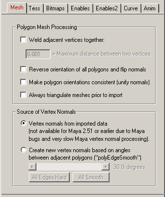
Weld Adjacent Vertices Together
If this checkbox is enabled (check-marked) then a vertex welding operation will be applied to all polygon vertices. Vertex welding collapses adjacent vertices which are within a distance less than or equal to the threshold value specified on the dialog box This welding operation should be performed if the Assign Smoothing Groups to Mesh Objects option (see below) is enabled. Note that welding of vertices can only occur within a single object and not between different objects. This option is enabled by default so that the Assign Smoothing Groups option works as expected.Maximum Distance Between Two Vertices
If the distance between two vertices is less than or equal to this number, and the Weld Adjacent Vertices Together checkbox is check-marked (enabled) then the two vertices will be collapsed (welded) into one.Reverse Orientation of all Polygons and Flip Normals
If this checkbox is enabled (check-marked) then the orientation of all polygons will be reversed. You might want to enable this option if you are finding that the Maya renderer is displaying only the back-facing polygons rather than the front-facing polygons.Make Polygon Orientations Consistent (Unify Normals)
For some 3d models, in particular those created using Autodesk's AutoCAD, there is no consistent orientation of the polygons; ie: some polygons of a surface are oriented clockwise (the geometric normal points inward) while the remaining polygons are oriented counterclockwise (the geometric normal points outward). This is a problem for the Assign Smoothing Groups to Mesh Objects option below since all of the polygons must have the same orientation in order for the smoothed vertex normals to be computed properly.If this option is enabled (checkmarked) then a special algorithm will be used to walk over the polygon mesh and reorient each polygon. Note, however, that adjacent polygons MUST share the same vertices for this algorithm to work; you can ensure that the vertices are shared by enabling the Weld Adjacent Vertices Together option above.
Always Triangulate Meshes Prior to Import
If this checkbox is enabled (check-marked) then all polygonal mesh data imported into Maya will first be triangulated (3 sided polygons). The default is disabled.Source of Vertex Normals
This section determines the source for the vertex normals assigned to each vertex of each polygon. The vertex normals can either come from the imported file, or they can be generated by Maya based on the angles between adjacent polygons.Vertex Normals From Imported Data
If this radio button is selected then the vertex normals are read directly from the input file.Create New Vertex Normals Based On Angles Between Adjacent Polygons
If this radio button is selected the Maya will compute the vertex normals automatically based on the relative angle between adjacent polygons. The angle is specified by the slider control; 0 degrees produces faceted models whereas 180 degrees produces perfectly smooth models. If you press the All Hard Edges button then the smoothing angle will be set to 0 degrees and the model will appear faceted. If you press the All Soft Edges button then the smoothing angle will be set to 180 degrees and the model will appear completely (overly) smooth.
This panel controls how NURBS surfaces are converted to polgyons during the import phase. It also controls the triangulation of mesh data (not related to the NURBS import process).
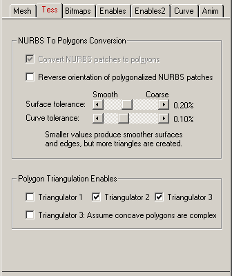
NURBS to Polygon Conversion Options
This import converter allows pure NURBS data to be imported from various file formats as polygon meshes.Convert NURBS Patches to Polygons
If this checkbox is enabled then all trimmed NURBS surfaces will be converted to polygon meshes prior to import into Maya. If this checkbox is disabled then the pure and unmodified trimmed NURBS surfaces will be imported directly into Maya.Reverse Orientation of Polygonalized NURBS Patches
If this checkbox is enabled then the orientation of all polygonzied NURBS surfaces will be reversed prior to import into Maya. This option should be enabled if only the back side of a NURBS object is visible when rendered with the Maya renderer.Surface Tolerance
Curve ToleranceThese sliders control the conversion of NURBS surfaces into polygons. The number of polygons used to approximate the true NURBS surface (or, its smoothness) is controlled by the Surface Tolerance slider. Lower values will make the surface smoother but at the expense of a longer tessellation time and more resultant polygons. This slider represents the maximum allowable distance (tolerance) between the true NURBS patch and the tessellated polygonal surface; it is measured as a percentage of an object's maximum bounding box size. For example, if a NURBS patch is being tessellated which is 10x10x10 units in size, and this slider is set to 0.2% then the resultant polygonalized surface will not deviate from the ideal NURBS surface by more than 0.02 units (2% of 10).Also, the Curve Tolerance slider is used to control the smoothness of the NURBS trimming curves. Smaller values will make trimmed curve regions smoother, but again at the expense of a longer tessellation time and more resultant polygons. This slider represents the maximum allowable distance (tolerance) between the true NURBS curve and the tessellated polygonal curve; it is measured as a percentage of an object's maximum bounding box size (the object on which the curve lies). For example, if a NURBS patch is being tessellated which is 10x10x10 units in size, and this slider is set to 0.2% then the resultant polygonalized NURB curve will not deviate from the ideal NURBS curve by more than 0.02 units (2% of 10).
Polygon Triangulator Enables
These options select which polygon triangulator will be used when a polygon mesh must be converted into a set of triangles during import (this only happens when importing a mesh with holes, or a mesh with intersecting line segments). Three different types are available. All handle n-sided geometry with recursive holes, but some are better than others for different mesh topology. If all 3 are enabled, then each one will be used in succession if a predecessor triangulator could not triangulate the mesh data.Triangulator 1
The first algorithm creates nicely triangulated meshes of n-sided concave polygons with optional holes but it cannot handle polygons with self intersecting edges or holes that intersect with the outer boundary. If it cannot triangulate the mesh data then triangulator 2 and then 3 will be executed next.Triangulator 2
The second algorithm is a more modern version of triangulator # 1. It should be able to handle all possible cases of triangulation, including self intersecting edges. This version will create new vertex locations when self intersecting edges are found, or it will remove vertices from the final triangulated mesh if it determines that such vertices are not required. If you want this triangulator to always work first, then disable triangulator # 1.Triangulator 3
This triangulator can handle any topology of polygon, including butterfly polygons (those that fold back on themselves), self-intersecting polygons and polygons whose interior holes intersect with its exterior boundary. In general, the newer triangulator # 2 should be used by default; however, triangulator # 3 is better than # 2 if you wish to use trapezoidal decomposition of the mesh.Triangulator 3: Assume Concave Polygons are Complex (slower)
If this option is enabled then triangulator # 3 will triangulate the polygon using a trapezoid scanline-based scheme which will allow any type of polygon to be triangulated but at the expense of creating less visually appealing triangle meshes. If disabled then the triangulator may not be able to triangulate butterfly polygons or simple polygons.
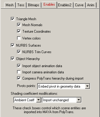

These check boxes control what type of data will be imported into Maya from the PolyTrans database.
Triangle Mesh
If this option is enabled (checkmarked) then all mesh (polygon) geometry will be imported from the file into Maya. If disabled then all mesh geometry will be ignored.Mesh Normals
If this option is enabled (checkmarked) then any vertex normals that are assigned to polygon vertices will be imported.Texture Coordinates
If this option is enabled (checkmarked) then any (u,v) texture coordinates that are assigned to polygon vertices will be imported. If this option is not enabled then texture maps will not appear on the polygon surfaces.Vertex Colors
If this option is enabled (checkmarked) then any vertex colors that are assigned to polygon vertices will be imported. There are not too many cases where you will find scene data that has vertex colors assigned to the geometry. However, some file formats, such as OpenFlight and Okino's BDF format do support vertex colors and such data can be imported through PolyTrans into Maya by enabling this option.Vertex colors can only be viewed in the shaded view windows of Maya, and only when the following series of steps are taken:
- Go into shaded mode by selecting Shading/Smooth Shade All from the view menu.
- Select the "Display/Custom-Polygon-Display/Square-Box" menu item from the main menu.
- On the Custom Polygon Display Options dialog box select these options:
- "Objects affected" = All
- "Color in shaded view" = check marked
- "Color material channel" = None
- Press "Apply" button on the Custom Polygon Display Options dialog box.
Skinning Weights
Enabling this option will turn on one of the most complex aspects of the PolyTrans-for-Maya export process, that of being able to import skinning weights associated with mesh data."Mesh skinning" is the process of deforming a single skin mesh with a skeleton or any hierarchical set of transform nodes. The contribution of each bone of the skeleton to the deformation of a vertex in the mesh is controlled by vertex weights.
Only skinned meshes are supported for import, not skinned NURBS surfaces or skinned curves.
Typical sources of skinned mesh data are 3ds Max, CINEMA 4D, Softimage, U3D, FBX, COLLADA and DirectX.
NURBS Surfaces
If this option is enabled (checkmarked) then NURBS surfaces will be imported. If disabled then NURBS surfaces will be ignored.NURBS Trim Curves
If this option is enabled (checkmarked) then trim curves will be assigned to their associated NURBS surfaces, if the curves exist. If disabled then no trim curves will be assigned to the NURBS surfaces.Object Hierarchy
If this option is enabled (checkmarked) then the hierarchical relationship of objects in the scene will be imported. This data will also use the scaling, rotation and translation data used by animation keyframe # 0.Object Animation Data
If this option is enabled (checkmarked) then object animation data which is currently contained within the internal database will be imported into Maya. Please note that this importer will most probably insert new nodes into the tree called anti-pivot nodes. These represent the object pivot point locations from the imported data file.Camera Animation Data
If this option is enabled (checkmarked) then camera animation data which is currently contained within the internal database will be imported into Maya.Remove Grouping (NULL) Nodes if No Children
This will prevent grouping nodes (NULL nodes, yellow folders, as they are all known) to be imported into the Maya hierarchy if they do not contain any subsequent children objects and the NULL node itself is not animated. It is enabled by default and it used to make the hierarchy cleaner. You may want to disable this in special cases, such as if a run of NULL nodes are used to represent a skeletal hierarchy.Compress PolyTrans Hierarchy During Import
If this option is enabled then PolyTrans will optimize its own internal object hierarchy tree when it is imported into Maya. Any combination of PolyTrans Null Node (empty folder, empty instance) followed by a child geometry node (mesh or NURBS object) will be converted into an equivalent Maya Transform Node plus Shape Node pair. In Maya the Shape nodes will be invisible, so the resulting "compressed" hierarchy will look cleaner.PolyTrans uses a hierarchy system based on a DAG tree. In this hierarchical system only null nodes can be connected to other null nodes to form the hierarchy of the geometry tree; this form is very similar to the DAG node hierarchy used by Maya. However, other popular 3D programs, such as 3ds Max and Lightwave, do not adhear to pure DAG hierarchies; these programs allow objects to be connected to objects, whereas in PolyTrans and Maya objects (shape nodes) can only be connected to their corresponding transform nodes (null nodes), and transform nodes can only be connected to transform nodes. In other words, PolyTrans and Maya only allow geometry nodes to be leaf nodes (the bottom most nodes) of a hierarchy tree while internal nodes of the tree can only be Transform node (or empty folders/instances in PolyTrans lingo).
Thus, when PolyTrans imports from such non-DAG system programs as 3ds Max, 3D Studio (.3ds) and Lightwave (.lwo, .lws), it has to change the non-DAG hierarchy into a DAG compliant hierarchy before the hierarchy can be stored within the PolyTrans internal database. To some people it may appear that PolyTrans has messed up the imported .3ds/.lw hierarchy trees. In fact, the hierarchy trees will be identical functionally and mathematically (all objects from the .3ds/.lw file will be leaf nodes of the tree, rather than internal nodes of the tree). If this option is enabled then the Transform node hierarchy shown within the Maya user interface should look identical to the original 3D Studio or Lightwave hierarchy (ie. no additional PolyTrans empty nodes should be visible).
Pivot Points
Pivot points are a fundamental component of an animation system. In the realm of the PolyTrans animation system pivot points define a local 3D coordinate system in space of an object about which the scale, rotation and translation animation function curves will be applied. The pivot point in PolyTrans is defined by a point in space and a local coordinate system defined by 3 orthogonal axes; the pivot point is defined relative to the local coordinate system of the mesh or NURBS geometry data. However, for programs such as SoftImage and Maya, the pivot point is defined to be the local origin of the raw mesh or NURBS data (no explicit pivot point location can be specified, as it can be specified in PolyTrans, 3D Studio and Lightwave).Since Maya cannot accept an arbitrary pivot point and pivot orientation, PolyTrans has to resort to other methods to get this pivot point information imported into Maya. Three options are provided, the first two which are identical except for method in which the pivot info is added to the scene graph:
Embed Pivot in Geometry Data
The inverse pivot matrix (which defines the location and orientation of the pivot point) is multiplied into the raw mesh vertices or the raw NURBS Cvs. This is only done (and only necessary) when the parent null node corresponding to this shape node is animated. This is the default option since it does not introduce any new anti-pivot nodes into the hierarchy tree.If it so happens that a PolyTrans null node (empty instance, empty folder) has animation on it as well as having a valid non-identity pivot matrix, then a child anti-pivot node is added to the tree; the child node is assigned the inverse pivot matrix and the original parent transform node gets the animation data. This properly applies the anti-pivot effect to the subsequent children in the tree.
Add Anti-Pivot Transform Node
A new "anti-pivot" Maya Transform node is introduced into the hierarchy tree, between the shape node (the mesh or NURBS geometry node) and the parent Maya Transform node which has animation on it. The inverse of the PolyTrans pivot point matrix is assigned to the transformation matrix of this new anti-pivot node. This new anti-pivot node acts to pivot-in the geometry vertices or Cvs prior to the animation data being applied to the geometry.Dont Output Pivot Points
This option prevents pivot point information from being output to the Maya scene. Normally you would never want to enable this option.Atmospherics & Backgrounds
If this option is enabled (checkmarked) then fog, mist and background color schemes will be imported into Maya. If disabled then these effects will be ignored.Materials
If this option is enabled (checkmarked) then materials will be created and assigned to the geometric objects in the scene. If disabled then no materials will be created.Bitmap References
If this option is enabled (checkmarked) then all 2D bitmap textures will be assigned to their associated materials. If this option is disabled then no bitmap references will be created and none will be assigned to the Maya materials (this basically disables texture mapping).Cameras
If this option is enabled (checkmarked) then the parameters of the current default camera will be imported.Lights
If this option is enabled (checkmarked) then ambient, point, directional and spot light sources will be imported.Dialog Boxes Shown During the Import Process
The following options control whether specific dialog boxes will be shown during the import process:Show Import Converter Progress Dialog Box
If this option is enabled (checkmarked) then a small status dialog box will appear while a file is being imported into the core PolyTrans software.Show PolyTrans to Maya Progress Dialog Box
If this option is enabled (checkmarked) then a dialog box will appear while the PolyTrans database is being imported into Maya. This is the second phase of an import process. This dialog box will describe which entity is currently being processed, the amount of memory currently being used and the overall completion status.Always Ask If Viewport is to be Auto-Resized
If this option is enabled (checkmarked) then a dialog box will be presented to the user every time a scene is imported into Maya. This dialog box will ask the user whether the current camera viewport should be auto-resized around all of the imported objects. If this checkbox is diabled then this dialog box will not be shown after the import process is completed and no auto-resizing will be done.Always ask to add default lights if none in scene
If this option is enabled (checkmarked) then a dialog box will be presented to the user every time a scene is imported into Maya if there are no lights in the scene. This dialog box will ask the user whether two or three lights are to be added to the scene automatically. If this checkbox is diabled then this dialog box will not be shown after the import process is completed and no lights will be added to the scene.Maya Animation Parameters Imported from File
The following checkboxes control how various animation user interface aspects of Maya are modified according to animation timing and extents data imported from the file.Time Units
If this option is enabled (checkmarked) then the Maya animation working time units will be updated to be equal to those imported from the file. For example, if the file uses 24 frames per second then the global animation time units will be set to Film (24 fps) in Maya.Playback Speed
If this option is enabled (checkmarked) then the animation frame rate from the imported file will be used to change the current global animation playback speed in Maya.Minimum/Maximum Playback Times
If this option is enabled (checkmarked) then the start/end of the imported animation data will be used to modify the minimum/maximum playback animation time limits in Mayas user interface.Start/End Extent Times
If this option is enabled (checkmarked) then the start/end of the imported animation data will be used to modify the animation start/end time limits in Mayas user interface.
The options on this dialog box control the most important aspect of the animation import/export conversion: keyframe resampling. NOTES:
- Camera animation keyframes will always be resampled when the imported keyframe lists do not use Euler orientations. Maya, internally, orients its camera using explicit (x, y, z) Euler angles. Other programs, such as 3D Studio, use explicit look-from, look-at and look-up vectors instead of explicit Euler angles. As such, these alternative methods of pointing the camera must be converted into Maya's Euler-angle compatible form via keyframe resampling.
- It is common in other 3D programs (such as 3D Studio) to animate a camera's field-of-view. However, in Maya, it is not possible to animate this attribute. Rather, Maya animates the focal length of the camera. Unfortunately, a camera's field of view and its focal length have a complex inverse mathematical relationship to each other. Importing an animation curve of a camera's field-of-view cannot be directly converted to an equivalent Maya focal length animation curve in a 1-to-1 manner. To solve this problem, PolyTrans resamples the imported field-of-view animation curve (say, from 3D Studio) at every frame then it warps each keyframe value of the animation curve using an inverse (1.0 / tan(field-of-view)) calculation. The result is a very accurate conversion of the field-of-view from other 3D programs to that in Maya. During our testings we have been able to import complex camera animations from 3D Studio (for example), including varying fields of view, and have the final rendered images inside Maya lock-up to the same camera orientation and view window aperture settings as from the source 3D animation program. This is one of the most complex animation conversion aspects of this software. Note that you will find the focal length animation channel in Maya has a sample at every frame; we decided not to enable keyframe reduction for this curve to improve the accuracy of image frame lock-ups.
These parameters control a process called keyframe resampling. Keyframes are snapshots of certain transformations in time, such as a rotation angle at time 0, time 10 and time 20. In many cases it is not possible to directly convert transformation keyframe data from one 3D animation program to another due to a difference in the underlying mathematics used by the respecitive animation program. For example, Lightwave and Maya store rotations as explicit Euler X, Y, Z angles, 3D Studio r4 stores rotations in angle/axis form whereas most modern animation programs store rotations in Quaternion form (DirectX, 3D Studio MAX and others).
To overcome the problem of converting keyframe data from one animation program to another, a complex algorithm was developed for this program which will resample the keyframe data from one format to another. For example, the quaternion angles of an imported 3D Studio animation can be resampled by this algorithm into equivalent Euler rotation angles for ultimate use in Maya.
Internally, this program (PolyTrans or NuGraf) has one of the most complex animation engines in any 3D program. This animation system allows all varieties of animation data to be imported from other 3D animation programs, previewed and exported to other file formats. Most importantly, the animation engine allows rotation data to be imported in Euler, Quaternion or Angle/Axis form then resampled to any other angular format.
The resampling process proceeds by creating a new, but temporary, keyframe list just prior to the animation import or export process. This new list has one key for each and every frame in the current animation. For example, if the original data had two keys at frame 0 and 60 that represented a 360 degree rotation, then the new keyframe list would contain 61 keyframes each representing a segment of the overall rotation animation. Since the internal animation engine can evaluate any rotation type (angle/axis, Euler or quaternion), this new keyframe list basically represents a new snapshot of the rotations at each and every frame in the animation. Once the new keyframe list is created the keys are converted to the desired export transformation method (such as angle/axis, Euler or quaternion when exporting rotation keyframes).
As an optional last step, this resampling algorithm can remove redundant keyframes from the new (but temporary) keyframe list. The optimized keyframe list will then exhibit similar behavior but with many fewer keyframes.
Dialog Box Options Re-Sample All Animation Data At Every Frame
If this checkbox is enabled (check-marked, which is the default) then all keyframe data will be re-sampled, as described above, prior to being exported. This re-sampling process is most useful when importing/exporting rotation keyframe data between programs such as DirectX, Lightwave, 3D Studio r4 and 3D Studio MAX. For example, this option allows 3D Studio r4 rotations (angle/axis notation with angles > 180 degrees) to be properly imported into Maya as explicit X,Y,Z Euler rotation angles.The three check boxes marked Translation, Scaling and Rotation allow the re-sampling algorithm to be applied selectively to the translation keyframes, the scaling keyframes and/or the rotation keyframes. These are all enabled by default.
As noted above, some animation import/export processes perform keyframe resampling regardless of the on/off nature of these three checkboxes. This is the case, for example, for camera orientation keyframe lists.
Time Interval To Perform Re-Sampling
These two radio buttons determine over which range of time the new re-sampled keyframes are to be created:
Within Time Extents of Each Keyframe List
Selecting this radio button will only re-sample each keyframe list over the time interval from its first keyframe time to its last keyframe time. For example, if the overall animation runs from time 0 to 100, but a rotation keyframe list only has keys from time 30 to 60, then the re-sampled keyframe list will only have keys in the tmie range 30 to 60.With Time Extents of Entire Animation
Selecting this radio button will re-sample all keyframe lists from the current start point of the animation to the current end point fof the entire animation. For example, if the overall animation runs from time 0 to 100, but a rotation keyframe list only has keys from time 30 to 60, then this option will cause the new rotation keys to be re-sampled and created for time 0 to 100. In many cases a keyframe list will have an implicit loop-around flag which allow a small number of keyframe to be looped indefintely. In such cases this radio button should be chosen so that the cyclical animation is captured in the re-sampled keyframe list. Take for example a bouncing ball for which the explicit animation keyframes are defined from frame 30 to 60 but which has a loop flag enabled so that the bouncing will continue indefinitely - if this radio button were not chosen then the exported animation data would only run from frames 30 to 60, but if this radio button were chosen then explicit keyframes would be created outside this range as well. In general, if you export some animation data and find that an object no longer moves or rotates then try enabling this radio button.Remove Redundant Keyframes From Re-Sampled Data
The re-sampling process creates one new keyframe for each frame in the current animation, hence there can be an overabundance of new keyframes in the exported animation. To alleviate this problem a robust keyframe reduction algorithm was written which intelligently removes some or most of the re-sampled keyframes. The resulting exported animation will exihibit the same or similar behavior, but with much fewer keyframes. If this checkbox is not enabled (not check-marked) then no keyframe reduction will be performed.'Distance' Difference Threshold
This numeric value indirectly controls how many redundant keyframes are to be removed from the re-sampled keyframe list. It is applicable to the following types of keyframe lists: translation, scaling, Euler rotation and path translation. Higher values will cause more keyframes to be removed. This value is the maxmum distance the new keyframe list is allowed to deviate from the original re-sampled keyframe list. Take for example a sphere that is animated along a path; if this threshold value is set to 0.5 distance units (which is the default) then redundant keyframes of the animated path will be removed until such point that the sphere begins to deviate by more than 0.5 units from its ideal location. In other words, if the value is set to 0.5 then you are guaranteed that the new reduced keyframe list will move the sphere along the same path in space, except that the sphere is allowed to deviate by 0.5 units from its original path. Smaller numbers will make the sphere adhear closer to its original path, but at the expense of retaining more keyframes.Angular Distance Threshold (Degrees)
This is the same as the previous numeric value except that it applies to reduction of quaternion and Angle/axis rotation keyframe lists. The value is measured in degrees. For example, if set to 5.0 (the default) then redundant keyframes will be removed from a keyframe list until such point that a rotation angle begins to deviate from its ideal angle by more than 5 degrees. Small numbers (such as 1.0 and 0.5) will cause less deviation and more precise rotation conversions, but at the added expense of retaining more keyframes.