| You are here: Home » Import CAD Formats » NGRAIN's 3KO Solutions |
|
This export converter writes out skeleton hierarchies and related IK information to the Biovision (BVH) and Acclaim (.amc and .asf) motion capture file formats. These file formats describe animated skeletons in terms of joints (Biovision), bones (Acclaim), hierarchy and angle constraints.
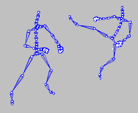
The following image shows an two skeletons of Kung Fu artists from a BVH file captured by Giant Studios (Motion Capture Data Provided by Giant Studios. All Rights Reserved.).

PolyTrans/NuGraf also includes a corresponding BVH/Acclaim importer.
Acclaim files have .asf and .amc file extensions. The .amc file will contain the motion capture data and the .asf file will contain the top level skeleton information data. The .asf file is the one which is typically loaded into the destination program,
One of the tasks of an Acclaim exporter is to add dummy bones to the hierarchy it exports. This is necessary since Okino's software is a joint-based system, which means it stores the hierarchy as a set joints. Acclaim file format, however, operates on bones, and thus each bone can have different characteristics and can be manipulated individually. Without adding the dummy bones, a case could arise where we would have a joint with two children. To be able to export each bone individually, we have to add another joint and make it a parent of one of the children (we insert dummy bones from the end of the parent bone to the child). This could be illustrated on the following example: The original hierarchy:
J1 ----- J2------J3 \___ J4The modified hierarchy:
J1 ------J2 ------ J3 \____D1___ J4(Where D1 is a dummy joint; note that D1 and J2 will have exactly the same position in the world space).
Note that if we rotate J2 in the original hierarchy, we will affect J4 also. However, J4 belongs to a different bone, so it should not be affected by the rotation of the bone defined as J2-J3. The creation of the dummy joint D1 allows us to separate the bones into J2-J3 and D1-J4, each independent of the other.
A skeleton is defined (in Okino software) as a series of connected joints. A joint is nothing other than a NULL node tagged as being part of a skeleton; it also has rotational and positional constraints. A bone is drawn when a child joint exists under a parent joint. The distance between the central pivot locations of the parent and child joints define the length of the bone. Rotational animation curves can be assigned to the parent joint to cause its child bone to become animated. Likewise, translational animation can be applied to the child joint to cause the length of the bone to become animated. Other 3D programs (such as LightWave) or file formats (Acclaim) work in terms of Bones and not joints; Okino software translates between external bones data and internal joint based data.

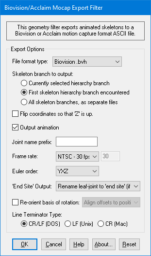
The following information explains the various options on the dialog box:
File Format Type
This drop-down box determines which file format to use during export. Biovision and Acclaim are two of the most popular and standard motion capture file formats.Biovision BVH
This outputs the skeleton data in the BVH file format. While not as complex or rich in context as the Acclaim format, it nonetheless seems to quite a universal format. BVH is a joint based format.Acclaim ASF and AMC
This outputs the skeleton data in the Acclaim file format. This stores the top-level skeletal information in a .asf file and multiple motion capture datasets in .amc files. Acclaim is a bones based file format.Skeleton Branch to Output
These radio buttons determine which branch(es) of the skeleton hierarchies currently inside the database will be exported.Currently selected hierarchy branch
If this radio button is chosen then the currently selected skeletal branch in the hierarchy will be exported only. This option only makes sense within the sfand-alone PolyTrans or NuGraf software since the concept of "selection" is that which is shown in the Selector Window of these two programs.First skeleton hierarchy branch encountered
If this radio button is chosen then only the first ROOT skeleton and its children will be output. BVH files can contain multiple ROOT objects, or in other words multiple skeletons (such as the 2 Kung Fu fighters shown above). Thus, this option will only output the first skeleton found in the hierarchy.All skeleton branches as separate files
BVH files can contain multiple ROOT objects, or in other words multiple skeletons (such as the 2 Kung Fu fighters shown above). The Acclaim file format can contain only a single ROOT object. If this radio button is chosen then multiple ASF/AMC file pairs will be generated (or BVH files if chosen), one for each ROOT object found in the hierarchy.Flip Coordinates so that Z is up
Flips the coordinates of all joints (including animation) so that the skeletons up direction is aligned with Z axis.Output Animation
If this checkbox is check-marked then animation will be output to the motion capture files.Joint name prefix
The string to be pre-pended to the name of each joint. If this field is empty, all the joint names are preserved. You may want to use this prefix in case you will be importing multiple motion capture datasets into the destination program for which the datasets use the same set of joint or bone names. Use this prefix to make each set of node names unique.Frame rate
The exported data is stored in terms of frames whereas animation inside Okino software is stored in terms of time. This drop-down box determines how time will be converted to frames during output. The default is 30 frames per second.** NOTE: You should ideally set this frame rate to the same frame rate inside your source application. For example, if you are exporting from Maya which is using 24 fps then set this exporter frame rate to 24 fps as well. This is the ideal case since then no inter-frame sampling will need to be done, and thus Euler angle conversion problems are much less likely to occur.
Euler Order
This sets the desired order for the Euler rotation angles as exported to the BVH file. The default is "YXZ".'End Site' Output Method
This combo box selects how the Biovision End Site node will be output, if at all.
As some background information, the bottom-most skeleton leaf node in a BVH file is supposed to be named as the 'End Site', such as in this example:
JOINT LeftMiddleEff { OFFSET 1.127769 -1.202957 -0.061024 CHANNELS 6 Xposition Yposition Zposition Yrotation Xrotation Zrotation End Site { OFFSET 0.0 0.0 0.0 } }However, two problems exist with the BVH 'End Site' node:
- It cannot contain any animation data. However, some animation programs allow animaton data to be applied to the last node in a skeleton hierarchy.
- It causes the last node in a skeleton hierarchy to be renamed to 'End Site' which some users of this BVH exporter may not want to happen.
Hence, this combo box of 3 output options has been provided to control how the 'End Site' node is output.
Rename leaf-joint to 'End Site' (if no animation)
If this combo box entry is chosen then the last exported joint node of a skeleton hierarchy will always be renamed to 'End Site' (if it does not contain any animation data).
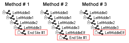
This is shown in the image below as Method # 1 whereby the bottom-most joint node has been renamed from 'LeftMiddleEff' to 'End Site #1'.
Output leaf-joint without name change. Output a new dummy 'end site' node
If this combo box entry is chosen then all joint nodes of the skeleton hierarchy will be output as-is and unchanged. However, to make the file compliant with the BVH file format, a new dummy 'End Site' node will be output as a child of each bottom-most leaf joint node. The dummy node will have a null OFFSET value. In other words, an 'End Site' node will be glued to the end of each joint hierarchy branch.
This is shown in the image below as Method # 2 whereby a new dummy 'End Site' node has been added to the bottom of the skeleton hierarchy (this new node is essentiall glued to the same location as 'LeftMiddleEff')
Output leaf-joint without name change. Do not output a new dummy 'end site' node
If this combo box entry is chosen then all joint nodes of the skeleton hierarchy will be output as-is and unchanged. Also, no new dummy 'End Site' node will be output. In theory, this is actually the best choice to make since it does not add any new useless (dummy) nodes to the file and it does not cause any of the source joint hierarchy nodes to be renamed to 'End Site'.
This is shown in the image below as Method # 3 whereby the skeleton hierarchy has been exported from the source program with no changes, and no new 'End Site' node has been output.

Re-Orient Basis of Rotation
"Align offsets to positive X-axis (3ds Max)" "Align offsets to positive Y-axis" "Align offsets to positive Z-axis" "Align offsets to negative X-axis" "Align offsets to negative Y-axis" "Align offsets to negative Z-axis" "Use frame zero as rotation basis" "Use bindpose as rotation basis (LightWave)"Each joint in a skeleton has a "basis" for its rotation values. That is, there is a certain direction which represents the "non-rotated" orientation of that node. This "non-rotated" orientation is then modified by the BVH motion data to produce the full animated motion.
Some third party programs are capable of directly reading BVH files. Some of these programs make assumptions about the basis of rotation used in any BVH file that they read. To facilitate interaction with such programs, the PolyTrans BVH exporter provides a number of choices for the "basis of rotation".
Many of the options allow the user to reorient the basis of rotation so that the "non-rotated" orientation appears along a specific axis in local-space. Character Studio of 3ds Max can benefit, for example, from files that are reoriented to "Align offsets to positive X-axis." This is because 3ds Max is designed to visualize its bones as extending along the positive X-axis by default. LightWave, on the other hand, visualizes its bones as extending along the positive Z-axis. If such an option is not enabled then the imported BVH files may have their bones pointing in all the wrong directions within 3ds Max or Lightwave, although the resulting skinned meshes may still behave properly (again, these are just problems related to how these programs "visualize" a virtual bone, not how they deal with mesh skinning).
As another example, the LightWave "MoCap_BVH_Setup" plugin can benefit from selecting either "Use bindpose as rotation basis" or "Use frame zero as rotation basis". Under the default options, MoCap_BVH_Setup will import a BVH file into LightWave with its BVH rotation basis loaded into frame 0 as animation and its BVH animation data beginning at frame 1. Selecting "Use bindpose as rotation basis" could facilitate the process of binding a new skin to the BVH data, since the bindpose data would be available at frame 0.
Note that PolyTrans supports direct import/export of skeletal animation data to and from LightWave. The above example is solely intended to help you understand the various values for the "Re-orient basis of rotation" option.
Use bindpose as rotation basis
Using this option will cause the BVH data to be reparameterized so that the first frame of animation (frame 0) will always be a skinned mesh's bind pose stance. For example, in MAX and Maya a skinned mesh and associated skeleton have a "bind pose" in which the character is in the DaVinci pose (arms stretched outwards). Frame 1 and onwards will have the normal BVH skeleton animation and position, but made relative to this initial bind pose basis.Use frame zero as rotation basis
Using this option will cause the BVH data to have the rotation data on frame 0 with all subsequent animation on frame 1 and onwards.In-Depth Explanation
A BVH file is partitioned into two distinct regions. The first region of the file defines the hierarchy of the skeleton. The second region contains the animation values for the defined skeleton hierarchy. When animation is disabled, or no animation data exists, the second region of the file must be empty. Also, applications capable of reading a BVH file will be aware of these different regions. Some BVH-reader applications might allow animation to be "turned off," and would then display only the data from the first region of the file.
The first region of a BVH file declares the hierarchy of the skeleton. It does this by defining the sequence of bones. Each bone is defined only by a translation offset from its parent bone. This still allows for an arbitrary skeletal structure, but it does not allow any rotation data. To be clear, the first region of a BVH file cannot represent any rotation data. Further, the second region of a BVH file can be empty or disabled in the target application. Thus, some BVH files will be incapable of representing any rotation data.
Rotation data is always relative to a "starting orientation." This "starting orientation" represents the identity rotation. Animation data is then applied to the "starting orientation" to produce the desired animation results. Examining the way in which BVH files work, we see that a non-animated file (e.g. a file with all identity rotations) will appear in the target application as it was defined in the first region of the BVH file. This non-animated hierarchy then defines the non-rotated case, to which any animation data would be applied.
Some target applications will load the first region of the BVH file into the frame zero transforms. Some applications provide a special "default, non-animated" frame of reference, and the first region of the BVH file will be loaded into those special transforms.
By default, the first region of the BVH file will contain the raw translation data (non-rotated) from your NuGraf/PolyTrans scene. In some cases, this is desireable. In other cases, the translations are relatively meaningless. For example, files originating in 3ds Max will have translations entirely along the X-axis; files originating in Lightwave will have translations entirely along the Z-axis. In both cases, the first region of the BVH file will define a skeleton which is entirely colinear along the axis in question.
One solution is to enable the "Use frame zero as rotation basis" mode. This uses advanced processing to adjust the translations and rotations of the skeleton nodes inside NuGraf/PolyTrans. It adjusts the data so that, instead of being potentially colinear along one axis, the raw translations (with no rotations) define a skeleton which appears to be like the one at frame zero in NuGraf/PolyTrans. This modified skeleton is loaded into the first region of the BVH file, so that the non-rotated skeleton hierarchy has a meaningful appearance (rather than being colinear sticks).
An alternate solution is to enable the "Use bindpose as rotation basis" mode. This functions in a similar manner to the "Use frame zero as rotation basis" mode. It adjusts the NuGraf/PolyTrans data so that the raw translations (with no rotations) define a skeleton which appears to be like the bindpose skeleton in NuGraf/PolyTrans (which is made visible by selecting the "Go to bindpose" menu option). This modified skeleton is loaded into the first region of the BVH file, so that target applications which load the BVH file will place the modified skeleton into their "special" or "frame zero" transforms. This mode has the special advantage that it allows the bindpose data to be cleverly encoded inside the BVH file. Otherwise, the BVH file is unable to represent bindpose data. Having the bindpose on hand can facilitate skin rigging at a later point.
Line Terminator Type
The character to use as a line terminator. Allows for selection between DOS, Unix, and Macintosh.
This is a snippet out of a larger BVH data file.
HIERARCHY ROOT Hips { OFFSET 0.000.00 0.00 CHANNELS 6 Xposition Yposition Zposition Zrotation Xrotation Yrotation JOINT LeftHip { OFFSET 3.29 0.00 0.00 CHANNELS 3 Zrotation Xrotation Yrotation JOINT LeftKnee { OFFSET 0.00 -16.57 0.00 CHANNELS 3 Zrotation Xrotation Yrotation JOINT LeftAnkle { OFFSET 0.00 -16.55 0.00 CHANNELS 3 Zrotation Xrotation Yrotation End Site { OFFSET 0.00 -3.30 0.00 } } } } JOINT RightHip { OFFSET -3.29 0.00 0.00 CHANNELS 3 Zrotation Xrotation Yrotation JOINT RightKnee { OFFSET 0.00 -16.51 0.00 CHANNELS 3 Zrotation Xrotation Yrotation JOINT RightAnkle { OFFSET 0.00 -16.69 0.00 CHANNELS 3 Zrotation Xrotation Yrotation End Site { OFFSET 0.00 -3.48 0.00 } } } } } MOTION Frames: 30 Frame Time: 0.033333 10.87 36.65 13.54 8.70 1.67 91.18 10.89 9.41 -1.80 -2.30 7.50 12.08 0.00 -10.56 0.00 -13.95 10.19 2.52 1.45 7.58 -10.90 0.00 -12.38 0.00 -2.30 7.22 -0.10 -0.13 0.00 5.48 48.69 -5.16 13.44 -10.40 -22.07 -14.50 -0.21 -5.66 -0.02 7.72 0.00 -7.17 -52.62 2.63 -1.95 -1.90 -20.04 -18.84 0.16 -4.85 0.01 0.00 35.36 0.00 1.77 -36.47 -2.39

