| You are here: Home » Import CAD Formats » CATIA v5 |
Support: 905-672-9328 Copyright © 2026 Okino Toronto, Ontario, Canada. |
|
This geometry import converter imports and processes BREP solids-based CAD geometry files stored in the CATIA v5 native part (.catpart) and assembly file (.catproduct) formats. The importer is based on the actual CATIA v5 runtime DLLs and components from Dassault Système (the developers and owners of the CATIA v5 modeling software) and hence provides the absolute best conversion of native CATIA v5 part and assembly files - no reverse engineered libraries are used, as is often the case with other CATIA v5 importers.
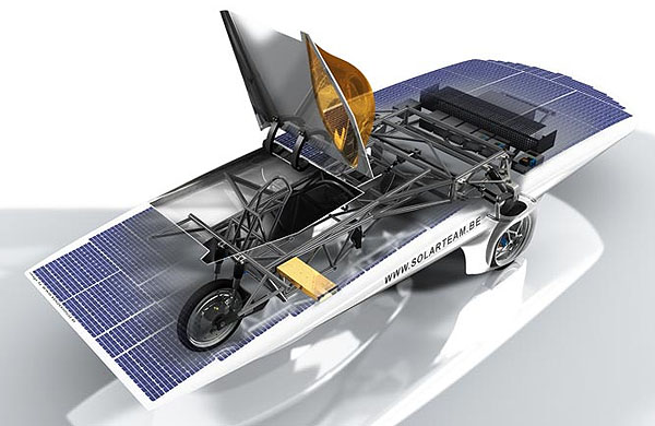
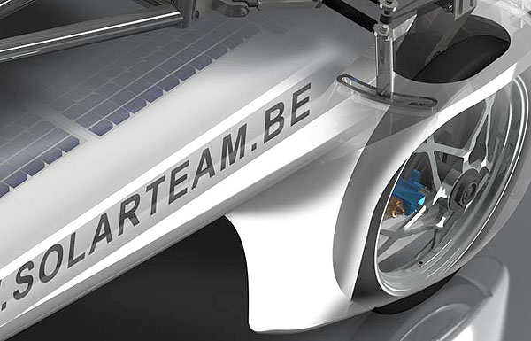
CATIA v5 models by Solarteam and Ludwig Desmet, Renderhouse BVBA. Click here for info.The CATIA stand-alone program (made by Dassault Systèmes and distributed by IBM) is an integrated suite of Computer Aided Design (CAD), Computer Aided Engineering (CAE), and Computer Aided Manufacturing (CAM) applications for digital product definition and simulation. It allows manufacturers to simulate all the industrial design processes, from the pre-project phase, through detailed design, analysis, simulation, assembly and maintenance. CATIA is primarily used by the automotive and aerospace industries for automobile and aircraft product and tooling design (it is well known for being used by Boeing to design their massive airplanes, or NASA to help design the Space Shuttle). There are roughly 20,000 companies worldwide using CATIA with roughly 30,000 seats sold per year.
Notes:
- If the file extension of your CATIA files end in ".model", ".exp", ".session" or ".dlv" then these are CATIA v4 files and not CATIA v5. In such a case you will need to use the Okino CATIA v4 importer.
- This is an optional add-on CAD module compatible with any Okino software.
- ** IMPORTANT ** Spatial Corp. licenses its CATIA v5 licenses on a per-year basis (this is not an Okino policy), with extensions via the yearly maintenance fee. Each year the license has to be renewed via the yearly 'maintenance fee'. Okino personally contacts its users of the Spatial CATIA v5 converters at month 11 and just before month 12 to remind them of the pending maintenance renewal. If the maintenance is not renewed then the CATIA v5 license will expire. Spatial Corp. requires that the maintenance fee be paid yearly, starting with the initial purchase. If you let the maintenance payment lapse (and let the license expire as a result), then decide to start paying them again at some undetermined time in the future to re-start the license, a "re-instatement fee" will then be due to Spatial Corp.
- This converter uses licensed components from Spatial Corp. If you encounter any problems loading a 3D model then please forward a problem report to support@okino.com and we will forward it to Spatial on your behalf.
- Okino has been a trained Spatial developer since 1997, resulting
in a top notch, refined and professional implementation
of the Okino-CATIA importer.
- Supports CATIA v5 parts (.catpart) and assembly (.cadproduct) files.
Assembly structure information is imported from .catproduct assembly files.
- Many options to control the import of the data. Import by body, face, bodies + faces or bodies + shells + faces. This allows rendering
materials to be applied at the finest granularity (faces) or the coarsest (bodies).
- Extensive tessellation controls.
- Model healing and erroneous surface repairs.
- Selective layer import.
- Importing via the CATIA "solids-based" file formats ensure that
adjacent NURBS patches are "stitched" together via topology information
(BREP data) and thus creates "crack free" tessellation when the NURBS
or parametric solids are converted to a polygonal mesh.
- The CAD importer includes a vital built-in Okino hierarchy/part
optimization
tool to reduce the complexity of the imported CAD files before
re-exporting to other 3D animation packages and downstream
file formats. This processing is particularly important when importing large CAD assemblies into Lightwave, 3ds Max and Maya.
This importer recognizes the following CATIA v5 file extensions, from versions R2 to current:
- .CATPart - CATIA v5 part file
- .CATProduct - CATIA v5 assembly file
If the file extension ends in ".model", ".exp", ".session" or ".dlv" then these are CATIA v4 files and not CATIA v5. In such a case you will need to use the Okino CATIA v4 importer.
Click on any one of the small screen snapshots to jump to the corresponding section of this WEB page:
| CATIA v5 | Transfer Control |
|---|---|
![[1]](imp_catia4_sml5.gif) |
![[2]](imp_catia4_sml1.gif) |
| Secondary | Tessellation |
|---|---|
![[3]](imp_catia4_sml2.gif) |
![[4]](imp_catia4_sml4.gif) |
Part Grouping Method
This combo box chooses how the imported geometry parts (the "bodies") will be connected into a hierarchy, or grouped together. Grouping by layer is the simplest method while the grouping by assembly hierarchy is the most complex and interesting.Group by layer number
If this option is enabled then the imported geometry parts (the "bodies") will be parented to the layer grouping names specified in the input file. If the input file does not contain any layering or assembly information then no grouping will be performed. CATIA v5 files have layers numbered from 0 to 999 and a "None" layer.
Group by assembly hierarchy
Group by assembly hierarchy. Append assembly definition nameIf this option is enabled then the imported geometry parts (the "bodies") will be parented according to the hierarchy defined by the .catProduct assembly.If the 'Append assembly definition name' additional option is chosen then the Okino instance names will have the CATIA v5 assembly's 'definition name' appended after the word "Defn:". This is purely for informational purposes and does not aid in the conversion process.
The following image shows the same assembly (as from the "Group by layer number" section above), but with the "Group by assembly hierarchy. Append assembly definition name" option enabled instead:
If the "Import Active Layer Only" checkbox is enabled then only the entities which reside on the "currently active CATIA v5 layer" are imported. This happens regardless of the option chosen from the "Part Grouping Method" combo box.
Exclude These Layers + Combo Box
If you wish to exclude one or more layers from being imported then click on the "Edit" button beside the drop-down combo box. This will pop up the following dialog box:
The numbers on the left side are the layers which were found in the source CATIA file (after the file is scanned) and which will be imported. The numbers on the right side are the layers which you wish to exclude (ignore) during the import process. To move layers between each listbox, do an extended listbox selection then press the "Add" or "Remove" buttons.
If the "Reset Ignored Layers To Empty When New File Chosen" checkbox is enabled, then the "Ignored Layers" list will be implicitly reset to empty status whenever you choose a new CATIA file to import. This is the default, since it makes sense that the 'layers to ignore' should be reset to empty whenever you import a new file. If you would like the 'Ignored Layers' listbox to remain unchanged as you select new and different CATIA files then keep this checkbox unchecked.
If the "Import Active Layer Only" checkbox is enabled then the exclusion list is ignored, and only the entities which reside on the "currently active CATIA v5 layer" are imported.
Name Reading Method
This is an expert-level option that you should never have to change. It determines how names for each imported object will be derived from the source CATIA file.
No Entity Names Generated
Each imported object will be named "Body". No attempt will be made to import any proper name for the object.
Element Name
Each imported object will be given the feature name as it was assigned in the source CATIA v5 file.
Publication Name
Each imported object will be given the custom (published) name as it was assigned in the source CATIA v5 file.
Element Name and Publication Name
Each imported object will be given the custom (published) name as it was assigned in the source CATIA v5 file followed by the feature name.
Import hidden items
If this checkbox is enabled then items which are marked as being "hidden" are not imported.
Repair erroneous surfaces
If this checkbox is enabled then the importer will check all the spline surfaces in the model and will attempt to correct them by using spline re-surfacing algorithms.
Create Log File
If this checkbox is enabled then a log file with the extension ".log" will be saved to the saved directory, and with the same filename, as the CATIA file being imported.
Write HOOPS .hsf File After File Import (for testing)
If this checkbox is enabled then a HOOPS .hsf file will be written to disk which mirrors the CATIA v5 file which was just imported. This is useful for testing purposes if you need to view the file in another application. A HOOPS .hsf viewer can be downloaded from www.hoops3d.com.
Re-Initialize CATIA v5 Environment Variables
This button causes the CATIA v5 runtime environment variables and runtime environment files to be re-initialized. The full process is outlined in this section: Setting up the Required Runtime Environment.
Normally the importer will perform these operations before each import process. You may want to do this manually if you find that the importer is not invoking the CATIA v5 runtime system properly.
Flip Model so that Y Axis is ‘Up’
If this option is enabled then the model will be rotated so that its “Up” axis is aligned with the positive Y axis instead of the positive Z axis.
Assign Materials at the 'Face' Level
If this option is enabled then materials will be allowed to be assigned at the "face" BREP object level. BREP objects are defined as bodies, shells and faces. If you import a model and find that some materials are missing then most probably they have been assigned at the lower level "face" level, in which case you will want to enable this option. This option is enabled by default.
Report Statistics About the Parsed File
If this checkbox is enabled then the import converter will print out the number of objects, polygons, normals, texture coordinates, tangent vectors and surfaces that were parsed from the input file.
Method to Import BREP Solids Objects
Solids-based CAD data is composed of “bodies” which contain one or more “shells”, and each shell contains one or more "faces". A body can be considered as an 3D object, and the faces can be considered at the sub-parts of the object. This is otherwise commonly known as a BREP, or "Boundary Representation" of a solids object.
This combo box determines how the solids-based BREP Body/Shell/Face entity will be imported and converted to the non-BREP polygonal form required by this destination program:
Single Body Parts (single BREP tesellation)
This option will create the least number of geometry items after import. If you feel that the model is still imported as "too many parts" then enable the "Optimize Object Count" checkbox.
This choice will cause all the sub-parts (faces) to be stored as a single object (ie: you won’t be able to move or modify the sub-objects of the body); this is useful if you don’t want dozens, hundreds or thousands of sub-parts cluttering your scene.
The "single BREP tessellation" variation will cause the faceter/tessellator to be applied to the top-most "Body" entity and not to each individual face (like as done in the next option below). This may result in better, crack-free tessellations.
Single Body Parts (via combined faces)
This is identical to the previous option above, except that the tessellation is applied to each individual face of the model and not to the body. After all the faces of the body are tessellated then they are combined back together into a single polygonal object.
Bodies + Faces (Lots of Objects)
This option will import the BREP "body" as many sub-parts (many BREP "faces"). It will tend to create a large number of child objects in the final scene. Choosing this option will provide the ultimate control over assigning materials to each face part of the BREP model, as well as allowing you to manipulate each face part.
Bodies + Shells + Faces (Lots of Objects)
This is the same as the "Bodies + Face" option except that another dummy level of hierarchy will be added between the "Body" definition and the list of "Face" parts in the hierarchy, with the name "Shell" on the dummy nodes. Basically this option will separate the Face parts based on the shell they are associated with in the Body part. Some people find this convenient if they model their parts based on "shells".
Optimize Object Count
By enabling this "Optimize Object Count" checkbox a series of algorithms will be invoked to combine all sub-parts contained within grouping nodes (under the yellow folder shown above) into respective single objects. In other words, the hundreds of sub-parts contained within grouping nodes will be reduced to single parts within each grouping node. In addition, once all the parts have been combined together, redundant grouping and hierarchy nodes will be deleted or merged.
In general this option only makes sense to enable when the "Method to Import BREP Solids Objects" combo box is set to "Bodies, shells and Faces" since this import method will create a huge number of "Face" objects.
For this importer it is not recommended that you need to enable this option. Instead, just set the "Method to Import BREP Solids Objects" combo box to "Single Body Parts" or "Single Body Parts + Shell Hierarchy". These options will implicitly import the least number of object parts.
The "Help" button which appears on the dialog box when this button is pressed describes the object and hierarchy compression algorithm further.
Match File Units to These Internal Units
"Units conversion" is often an important aspect of importing CAD files. People who create 3D models in a modeling package will do so using a specific units system, such as meters or feet. However, when these models are imported into another 3D package that uses a different default units system (such as Lightwave which uses centimeters), a "units conversion" operation needs to occur (the imported model geometry needs to be rescaled).
This option determines what will be done when the units defined in the source file do not match current internal program system units. If the units do not match, the importer will rescale the imported geometry based on the ratio between the source file units and the internal system units.
The drop-down combo box specifies the current units system in effect within the internal NuGraf/PolyTrans 3d database. It defaults to meters. What you need to do is select an appropriate entry from the drop-down combo box which matches the system units used by your destination program: for example, set it to Centimeters for Lightwave, Inches for 3DS MAX, Centimeters for Maya, etc (this should be automatic if importing into 3ds max or Maya).
None No units; never do any geometry scaling Custom Custom units are in effect. See below Microinches 1e-6 inches Mils 1e-3 inches Inches 0.0254 meters Feet 12 inches Miles 63360 inches Microns 1e-6 meters Millimeters 1e-3 meters Centimeters 1e-2 meters Meters Kilometers 1e+3 meters Custom Units in "Units Per Meter"
If the drop-down combo box is set to "Custom", then this edit text control defines the "units per meter" scale factor for the custom unit system.
Compute the Following Vertex Attributes
Vertex Normals. If this checkbox is enabled then the import converter will compute proper vertex normals for each triangle vertex. Vertex normals are necessary to make an object appear to be smooth when rendered.
Vertex (u,v) Texture Coordinates. If this checkbox is enabled then the import converter will compute proper texture (u,v) coordinates for each triangle vertex. Texture coordinates are necessary if a bitmap texture image is to be applied to the object at some time in the future.
Remove Duplicated Vertex Components For...
Vertices. If this checkbox is enabled then the import converter will remove any duplicated or redundant vertex coordinates. This will not modify the object but it may reduce the amount of memory required to store the imported model.
Vertex Normals. Likewise, if this checkbox is enabled then the import converter will remove any duplicated or redundant vertex normals.
Vertex (u,v) Texture Coordinates. Likewise, if this checkbox is enabled then the import converter will remove any duplicated or redundant vertex texture coordinates
Import Material Attributes (when available)
If this checkbox is enabled then additional rendering material attributes will be imported, if and only if they exist within the source data and are made available to this importer. Some of these attributes may include:
· RGB surface color
· Ambient, diffuse, specular and phong power shading coefficients
· TransparencyImport Lights (when available)
If this checkbox is enabled then lights will be imported, if and only if they exist within the source data and are made available to this importer. Point, spot, directional and ambient lights are supported.
An important aspect of this import converter is its surface tessellator. Almost all data imported from the source file is either “solid” entities or NURBS surfaces so this tessellator converts the implicit surfaces to n-sided polygons, quads or triangles during the import process.
The surface tessellator used in this import converter is the one provided by Spatial Technology. It converts the implicit surfaces to n-sided polygons, quads or triangles by applying the following refinement criteria, from highest to lowest:
1. Minimum number of U and V grid lines
2. Maximum edge length
3. Normal deviation
4. Surface deviation
5. Grid aspect ratioThe parameters on the right side of the dialog box control the surface refinement process.
Recommended Usage Method
- To make a bumpy or curved surface look smoother, move the 'Surface Deviation' slider more to the left.
- To make rounded edges or a curved surface look smoother, move the 'Normal Deviation' slider more to the left.
- To make 'quad-like' polygons and not a pure triangular mesh, with many of the resulting polygons have a squarish aspect ratio:
- Change the 'Polygon Type' combo box to Triangles on fringes only.
- Set the 'Minimum Grid Lines in U and V Directions' U and V values both to 10, or, change the 'Maximum Edge Length' to 0.1 (10%).
NOTE: If you wish to disable one or more of these refinement criteria then set the refinement parameter’s value to 0 (where possible).
Normal Deviation (Degrees)
This slider specifies the maximum deviation (in degrees) between the normals on two adjacent faces. Smaller values will make surfaces and curves smoother, but at the expense of creating more polygons. The default is 15 degrees and the range is 0 to 90 degrees.
15 degrees
1 degree
Surface Deviation (Percentage)
This slider specifies the maximum allowable distance between a polygon and the true surface, expressed as a percentage of the object’s bounding box size. Smaller values will make the model appear smoother, but at the expense of creating more polygons. The default is 0.2%.
0.1% deviation
1% deviation
Polygon Type
This combo box determines whether the tessellator will create triangles (3-sided polygons), N-sided (4-sided or more polygons) or a combination thereof.
Only triangles
This option will cause the tessellator to output the polygonal mesh purely as triangles.
N-Sided, Triangles on fringes only
This option will cause the tessellator to primarily output 4-sided quads or 5-sided polygons, except for the edge areas where some or all of the polygons may be triangles (to allow for smoother meshes).
N-Sided + Grid-to-edges
This option will cause the tessellator to output the polygonal mesh purely as a rectilinear grid of 4-sided quads or 5-sided polygons.
N-Sided + Quad-tree
This option will cause the tessellator to output the polygonal mesh purely as 4-sided quads or 5-sided polygons. However, an adaptive meshing algorithm (quad-tree or bin-tree) will be used to produce a more intelligent tessellation.
Less Commonly Modified Options
Minimum Grid Lines in U and V Directions
Spatial's tessellator is based on the concept of a rectilinear grid overlayed on the NURBS geometry which helps to determine how finely subdivided the geometry will become. Thus, this provides another mechanism to further subdivide the final polygonal facets.
In the following image, the number of grid lines is unconstrained (both of the parameter values set to 0).
Whereas in the following image, the 'Minimum Grid Lines' in the U and V directions have been changed to 10 (and the 'Polygon Type' was set to 'Triangles on Fringes Only'):
Maximum Edge Length
This slider specifies the maximum allowable length of any "edge", expressed as a percentage of the model's bounding box extents.
This image shows the result when this option is disabled. Notice the long triangles in the center flat region:
Edge length = 0 (disabled)
This second image shows this option set to 20%, which forces the model to be triangulated further so that no edge length is more than 0.2 times the size of the model's bounding box extents:
Edge length = 20%
The following is another example. In the first image the 'Maximum Edge Length' has been set to 0 (disabled):
Whereas in the following image, the 'Maximum Edge Length' has been changed to 0.10% (and the 'Polygon Type' was set to 'Triangles on Fringes Only'):
Smaller values (greater than 0.0) will cause more triangles to be created. A value of 0 disables this refinement parameter.
If modifying this option does nothing, then set the slider to increasingly smaller values (0.4% is the smallest input value possible).
Grid Aspect Ratio
This parameter specifies the approximate aspect ratio of each cell in the grid. If the value is close to 1 then the cell is close to a square. This does not guarantee the aspect ratio of the facet, which may consist of only a part of a cell.
Aspect ratio = 0.0
Aspect ratio = 1.0