

| You are here: Home » Import CAD Formats » DXF/DWG (AutoCAD & Others) |
Support: 905-672-9328 Copyright © 2026 Okino Toronto, Ontario, Canada. |
|
The Okino DXF/DWG import converter is one of the most mature and longest in development converters in the Okino software line. It has been fully implemented since its 1992 release date. It incorporates the newest DWG technology available each year, and hence can import, parse and create a highly optimized scene ready for re-conversion or immediate rendering. It is a particularly intelligent and complex converter which will read in DXF/DWG files containing 2d, 2-1/2d or 3d entities and transform them into optimized, grouped meshes of 3d polygons. Note: this is not a 2d to 2d vector converter, but rather deals entirely in the 3d domain.
The DXF/DWG importer has long been a staple 3D core importer for AutoCAD related conversions. However, as of 2009, our preferred method to have data brought out of Autodesk CAD products (in particular AutoCAD, REVIT and Navisworks) is via the DWF-3D file format and our very specialized Okino DWF-3D importer. For Autodesk Inventor, use the native Okino Inventor importer module. Both the DXF/DWG and DWF-3D import/export converters are provided in the Okino CAD/Pack module so that you can have the best of both worlds.
Please also refer to the corresponding DXF/DWG export converter.
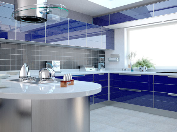
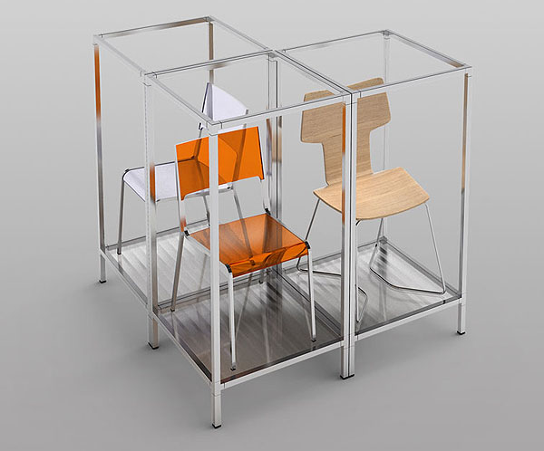
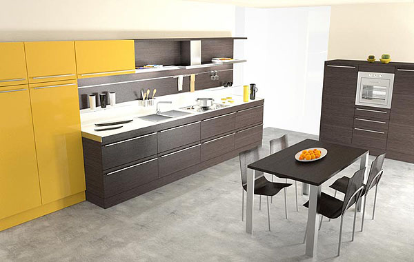
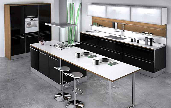
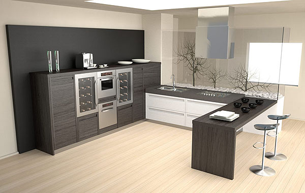
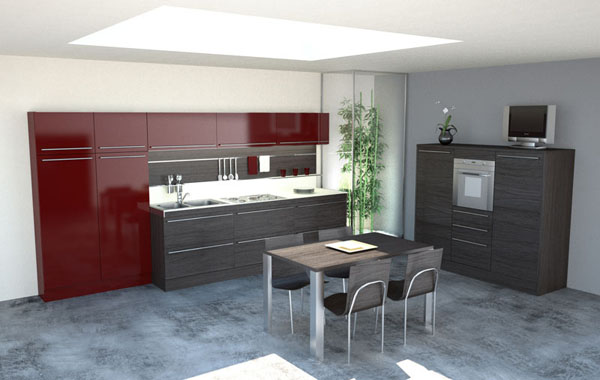
Architectural renderings by Segnoprogetto srl. Imported from AutoCAD to Cinema-4D.
See image collection here.
- Versions of DXF and DWG supported
- Highlights of the converter
- Supported Entities and their Conversion
- Special Treatment of DXF/DWG Entities
- Main Dialog Box Options
- Secondary Dialog Box Options
- 'ACIS Solids Tessellation' Dialog Box Options
- Welding, Unification & Smoothing Dialog Box Options
- Important Information on Welding/Unifying/Smoothing
- DXF ver 2.5 to 12 is supported in Okino's base package software.
- DXF R13 and newer, and all versions of the DWG file format, are only supported in the Okino "CAD/Pack" license configuration as this configuration uses a licensed third party toolkit to decrypt and parse DWG/DXF files.
- If the "CAD/Pack" license is installed then the following versions of DXF and DWG are supported during import: 2.5, 2.6, 9, 10, 11, 13, 14, 15/2000, 2002-201X (and all newer releases not mentioned here).
- Otherwise, DXF files up to R12 are support.
- And if ACIS solid entities are stored in the DWG file then they will be decrypted and turned into polygon meshes prior to import.
Whereas many DXF/DWG readers only read and convert 3D FACEs and 3d PolyMeshes, this converter will read in non-solids entities and convert them to 3d polygon equivalents. This includes processing all of the PolyLine attributes (bulges, line widths and thickness), PolyMesh types (mesh, face and lines) and 2d entities (lines, arcs and circles). In addition, the converter provides 5 powerful methods to "rip" apart the DXF/DWG file and convert it into separate objects. Also, if the DXF/DWG file uses blocks and instances then they will be converted into equivalent objects and instances within the converter's database - this will create a very small imported database since no data is duplicated unless necessary.
- Conformance to the AutoCAD DXF file format specifications.
- Reads both ASCII and binary versions of the DXF/DWG format.
- The 'Pre-Scan DXF/DWG File' option allows the DXF/DWG file to be pre-scanned for color
numbers, layer names and block names.
- Retains blocks and instances within the imported database (no object
replication).
- Handles externally referenced files, recursively. If the same file is referenced multiple times then it will
be converted to multiply instanced "master object definitions", and hence only one geometrical copy will be retained
in memory.
- Creates cameras from the VIEW entries found in the DXF/DWG file. The cameras
are compliant with the unpublished AutoCAD 'VIEW' algorithm for perspective
cameras.
- Reads in the most popular and important DXF/DWG entity and converts them into optimized 3d polygon meshes by a variety of means.
- Allows 2d entities with no width or thickness to be intelligently converted
into 3d polygons of very narrow width. This allows, for example, 2d
drafting diagrams to be imported and rendered in 3-dimensions. It can also
be used, for example, to import GIS data that consists of DEM terrain and
simple 3d polylines (very powerful!). This feature
is quite useful since 3D AutoCAD diagrams often use 2d lines and 2d
arcs to add fine detail to a scene; without this feature such detail would
be non-existent within the 3d imported scene.
- The converter is very memory efficient.
In order for the converter to accept an entity into its internal database the entity must be 3-dimensional. This excludes the direct importation of DXF/DWG arcs, circles, lines and polylines since they have no area. However, this DXF/DWG import converter performs a great deal of manipulation of these 2d entities so that they may be read in as 3d polygons. The conversion process is described as follows:
- arc - If an arc has 'width' then it will be turned into a series of polygons that approximate an arc of the desired width (all arcs of 0-width can be artificially widened so that they become 3d polygons by setting the 'line-arc-dummy-width' option non-zero). If the arc has thickness then it will be extruded in the 'Z' direction of the ECS (entity's coordinate system); in addition, if the 'add-end-faces' option is enabled then the top and bottom faces of the extruded arc will be capped with polygons. If the angle of the arc is 360 degrees then the arc will be replaced with a circle.
- circle - If a circle has no thickness then it will be converted into a flat 3d 'disc' which approximates a circle with a series of polygonal faces. If the circle has 'thickness' then it will be extruded into a hollow cylinder with no ends caps unless the 'add-end-faces' option is enabled.
- line - If a line has 'width' then it will be widened into a 3d polygon (of varying start and end widths). If the line has 'thickness' then it will be extruded in the 'Z' direction into a single 3d polygon or a series of 3d polygons defining a volume. If a line has no width or thickness then it will be rejected by the converter unless the 'line-arc-dummy-width' option is set non-zero in which cause the line will be artificially widened into a very thin polygon; this latter option allows a 2d flat drafting diagram (for example) to be turned into very thin polygons that can be subsequently rendered in a 3d rendering program.
- 2d and 3d polylines. If the polyline has a non-zero 'bulge' factor in any of its segments then those line segments will be replaced with segmented arcs. If any line segments have a non-zero 'width' factor then those line segment(s) will be replaced with 'fat line' segments represented as planar 3d polygons. If any line segments have a non-zero 'thickness' factor then a 2d line segment will be extruded upwards in the 'Z' direction to form a 3d polygon, whereas a previously pre-widened 3d polygon (a line with a non-zero 'width' factor) will be extruded upwards in the 'Z' direction to form an enclosed volume defined by a number of polygons. If a polyline is not CLOSED, and it does not have any width or thickness then the converter will not import it into the 3d database (note, however, that if the 'line-arc-dummy-width' option is set non-zero then such 2d lines will be widened into very thin 3d polygons).
- polyface mesh. This is a series of vertices and their associated face indexes that compactly specify a 3d object. This entity is very similar to the 'IndexedPolygon' primitive used internally within the converter's database and as such this entity converts with little change.
- polygon MxN mesh. This is a uniform grid of 3d polygons. The converter handles the optional closure of the mesh in the M, N or M&N directions. The entity is converted directly to the converter's internal 'IndexedPolygon' primitive.
- 3D face - 3d faces are collected and stored together as 3-point or 4-point polygons in objects using the converter's internal 'IndexedPolygon' primitive.
- trace - traces are 4 sided line segments with non-zero widths which get converted to equivalent closed 3d polygons.
- solid - solids get converted to 3 or 4 sided polygons. Do not confuse the 2d simplistic 'solid' with AutoCAD R13's 3D Solid primitives (ACIS solids).
- insert - Blocks will be inserted with scale/rotate/translate transformations and optionally the converter can instance a block several times in a MxN grid. Note that instancing a block will not duplicate the block geometry data within the converter's internal database - rather, instances will be created of the imported block just as with AutoCAD.
The 2d polyline is given "extra special" treatment by the DXF/DWG converter.
- First, all bulges in the polyline are converted to arc segments.
- Next, the converter orients all of the resulting line segments of the polyline so that they are connected in a head-to-tail fashion (a requirement of a 3d polygon).
- Finally, the converter removes any redundant vertex coordinates (such as the last one in the list) so that the vertices form a valid 3d polygon.
- If the polyline has thickness (but no width) then the polyline is extruded into a 3d volume and directly stored in the converter's internal database as a highly efficient and verified mesh primitive.
- If the polyline has width then it will be stored as a series of less-efficient individual polygon faces.
Since a polyline with extrusion is commonly used to create 3d objects within an AutoCAD drawing, these processing steps ensure that the resulting imported data will result in good 3d renderings of such data.
Pre-Scan DXF/DWG File button
If this button is pressed then the file will be scanned and the color numbers, layer names and block names referenced within the file will be displayed on the right side of the dialog box. No data will be read into memory. This option is quite useful if you would like to know how the DXF/DWG file is structured.Object Creation Method
This is a very important option which basically determines how the DXF/DWG converter is to turn the "mess" of 2d and 3d drawing entities contained in the DXF/DWG file into nice and orderly 3d objects. You must decide which method is best to turn the file into 3d objects - this is best done by running the converter first with the 'Pre-Scan DXF/DWG File' option described above which will list out all of the color numbers, block names and layer names used in the file. From this information you should be able to decide which method is best (for example, if the entities are grouped by layer name in the file then choose the "By Layer Name" option).Each entity in AutoCAD (ie: a line, PolyLine, 3D Face, a mesh) has a number of attributes associated with it which include its "layer" name, its "color" number and which "block" it belongs to (entities are not always contained in blocks).
- The 'By Block Name' option will create one new object for each block contained in the DXF/DWG file. If an entity is not associated with a block then it is added to a separate object named "non-block entities".
- The 'By Layer Name' option will create one new object for all entities which belong to the same layer in the DXF/DWG file. If an entity is not associated with a layer then it is added to a separate object named "lone entities layer".
- The 'Extract from One Specific Layer' option is similar to the 'By Layer Name' option except that only entities that belong to the layer specified in the 'Extract One Layer name' type-in box will be imported. This option is useful is you only want to convert a specific layer.
- The 'By Color number' option will create one new object for all entities which belong to the same color number in the DXF/DWG file. The objects will be named as 'color x' where 'x' is the AutoCAD color number.
- The 'Create One Object By Entity' option will create one object per entity contained in the DXF/DWG file. Normally you should NOT use this option since a DXF/DWG file typically contained tens of thousands of entities. However, if you know that the file contains only meshes, or only a few entities, then this option might be useful.
- The 'Create One Single Object' option creates only ONE object which contains every entity found in the DXF/DWG file.
Material Creation Method
This is the second most important option which determines how the DXF/DWG converter is to be create and assign new materials (surfaces) to the new objects created.
- The 'By Block Name' option creates one new material for each block name found within the DXF/DWG file. These new materials will then be assigned to the entities which belong to each block. If an entity does not belong to a block then it will be assigned the "default" surface. The material name will be the same as the block name.
- The 'By Layer Name' option creates one new material for each layer name found within the DXF/DWG file. These new materials will then be assigned to the entities which belong to each layer. If an entity does not belong to a layer then it will be assigned the "default" surface. The material name will be the same as the layer name.
- The 'By Color Number' option creates one new material for each unique AutoCAD color number which was referenced in the DXF/DWG file. These new materials will then be assigned to the entities which use the referenced color numbers. The material name will be created using the syntax "color xx" where "xx" is the color number.
- The 'One Material Per Entity' option creates and assigns one new material for each entity within the DXF/DWG file. The material name syntax will be "entity xx". Normally you should NOT use this option since a DXF/DWG file typically contained tens of thousands of entities. However, if you know that the file contains only meshes, or only a few entities, then this option might be useful.
- The 'Assign Default Material' option assigns the "default" material (surface) to the entities in the DXF/DWG file. This option is useful is you will be creating your own materials and assigning them to the imported objects yourself.
Add Caps To Extrusions
If this checkbox is enabled (check-marked) then polygon end caps will be added to 2d entities which have been extruded, such as arcs and circles. For example, an extruded circle will remain a hollow cylinder if this option is un-checked, else it will become a closed cylinder with each caps if this option is this option is check-marked. This option is disabled (un-checked) by default since some DXF/DWG files do not look good with this option enabled.Read Camera Views
If this checkbox is enabled (check-marked) then the converter will parse the DXF/DWG "VIEW" table entries and convert them to camera definitions.List Parsing Statistics
If this checkbox is enabled (check-marked) then the converter will print out information about the parsing process after the DXF/DWG file has been parsed and read into memory.List Block and Layer Names
If this checkbox is enabled (check-marked) then the import converter will print out the names of the blocks and layers found within the DXF/DWG file after it has been parsed and loaded.Scene Scaling Factor
This option allows the imported scene to be scaled larger or smaller by a user specified amount. As examples, enter these values: 1.0, no scene scaling 1000, scale 1000 times larger 0.001, scale 1000 times smaller 4, scale 4 times larger 0.25, scale 4 times smaller You can enter a value into the edit box specifying a relative scaling factor, and the model will be scaled by this factor. For example, if you enter '2.0', the model will come out twice as large.Match Units From Source File to Internal Systems Units
Quick Explanation
DXF and DWG files have no explicit "units" specified in them. When a person does modeling in AutoCAD there is no explicit units defined for the scene; the user themselves only have an understanding (implicitly) of the units being used for the scene.These 2 combo boxes allow you to specify what you believe the units should be for the source DXF/DWG file and to optionally modify the units being used for the destination scene. By doing so, the imported data will be scaled larger or smaller in size to match your desired system units.
Quick Usage Explanation
Set the "Assumed units for DXF/DWG file" combo box to the units you believe the source file was created in. This defaults to meters.The "Internal System Units" combo box usually does not need to be modified. This shows the current units being used by the destination scene. For example, if you are importing into Maya using the PolyTrans-for-Maya native plug-in then this combo box defaults to "centimeters"; if you are importing into 3ds Max using the PolyTrans-for-MAX native plug-in then this combo box defaults to "inches".
Full Explanation
This option allows the scene to be scaled larger or smaller, to match a "desired" units of measurement compared to that which the DXF/DWG file was originally created in. For example, if you select "meters" for the "Assumed units for DXF/DWG file" combo box and "kilometers" for the "Internal System Units" combo box then the scene will be scaled 1000 times smaller before being imported.AutoCAD does not define an explicit unit of measurement inside its modelers so you need to explicitly specify the units of measurement via the " Assumed units for DXF/DWG file" combo box.
"Units conversion" is often an important aspect of importing DXF and DWG files. People who create 3D models in a modeling package will do so using a specific units system, such as meters or feet. However, when these models are imported into another 3D package that uses a different default units system (such as Lightwave which uses centimeters), a "units conversion" operation needs to occur (the imported model geometry needs to be rescaled).
This DXF and DWG import options panel determines what will be done when the units defined in the DXF/DWG file does not match current internal system units. If the units do not match, this importer will rescale the imported geometry based on the ratio between the DXF/DWG units and the internal system units.
If this checkbox is enabled then the DXF/DWG importer will rescale all imported geometry so that the units of the file can be made to match the units of the internal NuGraf/PolyTrans/Maya/3ds-max database. If the checkbox is disabled then the geometry will be imported unchanged and untouched, meaning that its scale may be "incorrect".
Assumed units for DXF/DWG file Combo Box
This drop-down combo box specifies the units measurement system which you believe the source DXF/DWG file was modeled in. See the next paragraph for an explanation of each entry within this combo box.Internal System Units Combo Box
This drop-down combo box specifies the current units system in effect within the internal NuGraf/PolyTrans/Maya/3ds-max 3d database. It defaults to meters. What you need to do is select an appropriate entry from the drop-down combo box which matches the system units used by your destination program: for example, set it to Centimeters for Lightwave, inches for 3ds Max, centimeters for Maya, etc. Normally you would not need to modify this for Maya and 3ds Max.
None No units; never do any geometry scaling Custom Custom units are in effect. See below Microinches 1e-6 inches Mils 1e-3 inches Inches 0.0254 meters Feet 12 inches Miles 63360 inches Microns 1e-6 meters Millimeters 1e-3 meters Centimeters 1e-2 meters Meters Kilometers 1e+3 meters Custom Units in "Units Per Meter"
If the drop-down "Internal System Units" combo box is set to "Custom", then this edit text control defines the "units per meter" scale factor for the custom unit system.
External References Processing Mode
This combo box determines how "external references" in the main DXF or DWG file are to be handled.Import as explicit, embedded data
This mode recursively imports the DXF/DWG file and all of its external references so that the files become imported as one main scene.Note: A META data tag named "XREF-FILENAME" will be assigned to the top-most node of each imported external reference (the empty instance with the tag of "(xref)" on them), with a string name of the corresponding DXF or DWG filename. A custom exporter can use this META data to recreate the XREF association during export.
Import as 'grouping nodes' with no data
This mode recursively imports the DXF/DWG file and all of its external references, but only places a single 'Empty Instance' node (yellow folder) in the scene where the externally referenced file would normally be imported and added to the scene graph. The 'insert' transformation will be assigned to this empty instance node.Note: A META data tag named "XREF-FILENAME" will be assigned to these empty instances (yellow folders) with a string name of the corresponding DXF or DWG filename. A custom exporter can use this META data to recreate the XREF association during export.
Do not import any external references
This mode causes the external references of the main DXF/DWG file to be ignored. No external references or any related information will be imported.Maximum Recursion Depth
This type-in box determines how deep the importer will traverse into nested external references. If set to 0 then there is no limit. If set to 1 then only the first XREFs at the top hierarchy level will be imported. If set to 2 then the first XREFs at the top hierarchy level will be imported as well as their first children. And so on.Reverse Orientation of Polygons (Flip Normals)
If this checkbox is enabled (check-marked) then the orientation of all polygons will be reversed. You might want to enable this option if you are finding that a 3d renderer is displaying only the back-facing polygons rather than the front-facing polygons.Ignore Layers Which are 'Off'
If this checkbox is enabled (check-marked) then entities which reside on layers which are "off" will be ignored.Ignore Layers Which are 'Frozen'
If this checkbox is enabled (check-marked) then entities which reside on "frozen" layers will be ignored.Output verbose parsing information to file 'debugdxf.txt'
If this checkbox is enabled (check-marked) then verbose parsing information will be output to the ASCII file 'debugdxf.txt' located within the current working directory. This option is disabled by default.Print Warning Messages from the Parser
If this checkbox is enabled (check-marked) then the parser will print out warning messages encountered during the parsing process. This option is disabled by default.Import Text Elements
This checkbox determines if DXF "2D TEXT" will be imported. If enabled, DXF 2D vector text will be imported as the Okino "3D TrueType text" geometric primitive. This primitive will create renderable, polygonalized 3D text. It will not display the text using flat, vector/bitmap text. Only limited alignment methods from the DXF/DWG file are supported.TrueType font names are supported, not SHX vector fonts. If the "style" associated with the text in the DXF/DWG file references a TrueType font filename, and that filename exists on your computer, then it will be assigned to the imported text. If you wish to override all imported fonts with your own font of choosing, then press the "Choose" button. "Arial" will be used by default if no font is chosen and no font is found in the DXF/DWG file. To go back to using the DXF/DWG file's font instead of your own font, press the "Reset" button on the options dialog box.
Width for 2d lines/arcs
This value controls an interesting aspect of the DXF/DWG converter. If this option is set greater than 0.0, and a 2d line has no width or thickness, then the converter will artificially widen the 2d line into a rectangular 3d polygon which has a width equal to the value set by this option and a length equal to original line length. This option is useful because it allows 2d lines (which implicitly have no area) to be rendered in a 3d renderer which only accepts 3d polygons (with an area).This value should be set non-zero if you want 2d line segments to be turned into polygons which will be visible within a 3d rendering. If you set the value to 0.0 then the 2d line segment will be thrown away. The magnitude of this parameter should be set fairly small compared to the overall size of your scene's 3d size (ie: 0.01 for a 10x10 scene). For example, a DXF/DWG file was loaded in which contained a street map; the overall size of the "world" was about 500,000 x 500,000 units - in this case the 'Width for 2d lines/arcs' parameter was set to 5 so that the streets (which were polylines) could be rendered in 3d.
Segments per Arc/Circle
This parameter determines the number of straight line segments that an arc or circle should be broken into, per 360 degrees. For example, a circle uses an angle of 360 degrees so it would be broken into 30 line segments, whereas an arc of angle 90 degrees would be broken into 8 line segments.
This dialog box controls the tessellation of the ACIS solids entities from the source file. "Solids" are a BREP (boundary representation) type of geometry that allows "water right, crack free" geometry to be created from pseudo "solids". This is the type of geometry used by most high-end 3D CAD modeling systems.
When these entities are imported they must be converted to a polygon mesh. The density (number of polygons created) is controlled by the following parameters. The default values should produce good quality files.
Normal Deviation (in degrees)
This slider specifies the maximum deviation (in degrees) between the normals on two adjacent faces. Smaller values will make surfaces smoother, but at the expense of creating more polygons. The default is 15 degrees and the range is 0 to 90 degrees.15 degrees
2 degrees
Number of grid lines between NURBS knots
For NURBS surfaces (and not ACIS solids), this value defines how many additional grid lines will be placed between each NURBS knot value. A value of 0 will place the grid lines coincident with each knot value in the uv space of the NURBS surface. A value of 1 will add one new grid line between consecutive knot values. This aids to subdivide a NURBS surface in a further level of subdivision.Number sample points per edge
This parameter allows you to explicitly control how many sample points will be taken around curved edges. For example, if there is a hole in the middle of a plane then this type-in value determines how many points will be sampled along the hole - higher values will make the hole appear to be smoother since more sample points are being taken. A value of 0 (the default) will automatically sample the curve at an internal epsilon distance along the curve.Maximum facet edge length
This value specifies the maximum allowable length of any "edge".This image shows the result when this option is disabled. Notice the long triangles in the center flat region:
Edge length = 0 (disabled)
This second image shows this option set to 1.0, which forces the model to be triangulated further so that the edge lengths are approximately the same.
Edge length = 1.0
Values must either be 0.0, or >= 1.0. A value of 0 disables this refinement parameter.
The following options are applicable once the DXF/DWG file has been read into memory but before the resulting polygonal data has been stored within the converter's internal database. See the Important information section for background information on welding, normal unification and normal smoothing.
Weld Vertices, Threshold = #
If this checkbox is enabled (check-marked) then the vertex welding operation will be applied to all polygon vertices once the DXF/DWG file has been read into memory and the objects created. Vertex welding collapses adjacent vertices which are within a distance less than or equal to the threshold value specified on the dialog box This welding operation should be performed if the 'Smooth Data' option (see below) is enabled. Note that welding of vertices can only occur within a single object and not between different objects. Also, the welding operation can become quite slow for objects with large number of vertices since every vertex must be compared against every other vertex (an n-squared problem). This option is disabled by default.Threshold Value Type-In
If the distance between two vertices is less than or equal to this number, and the 'Weld Vertices' checkbox is check-marked (enabled) then the two vertices will be collapsed (welded) into one.Unify Normals
If this checkbox is enabled (check-marked) then the DXF/DWG import converter will walk across the polygon mesh and reorient each polygon so that it has the same orientation as its neighboring polygon(s). This "unification" process if often necessary because 3d models created with AutoCAD typically do not have any consistent polygon orientation (ie: some polygons are oriented clockwise while other are oriented counter-clockwise). Consistent polygon orientation is a prerequisite for the 'Smooth Data' option (described below).Notes:
- This function will only work if neighboring polygons share the same vertices; if this is not the case then enable the 'Weld Vertices' option described above.
- The unification of normals can only occur within a single object and not between different objects.
- This option is enabled by default and should be quite fast for most objects.
- The option should NOT be enabled if any of the DXF/DWG entities are AME solid models in which case you should unify the objects on a one-by-one basis (such as with the NuGraf software or within 3D Studio).
Orient Normals Outward
In some cases the 'Unify Normals' option described above will flip all of the geometric and vertex normals so that they point inwards towards the center of each object. If this occurs then this option should be enabled (checkmarked) so that the majority of the normals point outwards.Orient Normals Inward
This option can be enabled to cause the majority of the polygon normals to point inward toward the centroid of the object. Normally you would want to enable the 'Orient Normals Outward' option instead.Smooth Data, Angle = #
If this checkbox is enabled (check-marked) then new vertex normals will be computed for a polygon if it does not have any vertex normals already. The smoothing criterion is based on the angle between adjacent polygons; common smoothed vertex normals will be computed if the angle between their geometric surfaces normals is less than the 'Smoothing Angle' type-in value described below.If this checkbox is disabled (un-checkmarked) then no new vertex normals will be created.
NOTE: for this option to work properly the input data must have its vertices welded together so that adjacent polygons share the same vertices (the 'Weld Vertices' checkbox must be enabled (check-marked)). You may optionally have to enable the 'Unify Normals' option so that the polygon normals are oriented properly in order for the smoothed vertex normals to be computed. This option is enabled by default.
Smoothing Angle Type-in
This type-in value sets the cut-off smoothing angle (in degrees) used by the vertex normal computation algorithm. If the angle between two adjacent polygons is greater than this number then no smoothing will occur (a crease will be evident between the two polygons), else smoothing will occur where the polygons meet. The default angle is 45 degrees; higher values will make the surface smoother.Optimize Hierarchy and Node Count
Enabling this checkbox allows a post-processing operation to take effect which removes redundant grouping folders from the imported scene hierarchy. Press the "Options..." button and then the "Help" button on the second dialog box to get full help. Normally you would not need to enable this option on the DXF/DWG importer since these files do not have hierarchy in them. However, it can come in handy when there are external references and you wish to remove the "Red folders" from the scene hierarchy as viewed inside of Okino software.
If the imported DXF/DWG data is to be sent to a 3D renderer for rendering then it is quite important to understand the concepts of welding, unifying and smoothing.
Except for DXF/DWG meshes, AutoCAD entities are imported and converted into 3-point or 4-point planar polygons. Since the polygons are created on a one-by-one basis no polygons share the same vertex coordinates as any other polygons, even though they may appear to share the same vertices. In order for the normal unification and smoothing code to work all polygons must be welded together so that adjacent polygons share the same physical vertices (the result is similar to an AutoCAD mesh where all of the vertices are shared between polygons). This welding is achieved by enabling the 'Weld Vertices' option and setting the 'Weld Vertices Threshold' value to an appropriate value. If you know that the input data only uses polygon mesh entities then this welding operation is not required.
If the distance from one vertex to another is less than or equal to the 'Weld Vertices Threshold' parameter then the two vertices will be collapsed into one, else the two vertices will be kept unique. After you import a DXF/DWG file you may find that some or all polygon faces did not get smoothed properly; this is an indication that the threshold parameter was set too small since the polygons did not get welded together. In this case examine the imported model and try to determine the maximum distance between adjacent un-welded vertices and try re-importing the model again with the new threshold parameter value.
The next (optional) step after having the vertices welded is to unify the polygon normals. A "polygon normal", in the simplest terms, is a line sticking out perpendicular from the "outside face" of a polygon. The orientation of this polygon normal is important to some rendering programs since they will throw away polygons which have their normals facing away from the camera (termed "backface culling") in order to speed up the rendering process. Unfortunately, many DXF/DWG files contain polygons which have random polygon normal orientations. The converter can attempt to "unify" or re-orient these normals by having the 'Unify Normals' option enabled. By doing so the converter will walk across the polygon mesh and reorient each polygon so that all adjoining polygons share the same orientation.
The last step is to smooth out the data. "Smoothing" is the process of creating artificial normals for each polygon vertex which will be used by a rendering program to make a faceted model appear to be completely smooth. These vertex normals are used, for example, to make a sphere appear to be smooth when in fact the sphere is made up of flat polygons. The import converter can attempt to create smoothed vertex normals by having the 'Smooth Data' option enabled and by setting the 'Smooth Data Angle' type-in value to an appropriate angle (defaults to 45 degrees). See the appropriate options in the Welding, Unification and Smoothing Options section for an explanation of these options. NOTE: a polygon's vertices must be welded together and its polygon normal unified before the smoothing operation can be applied to it.