

| You are here: Home » Products » PolyTrans|CAD+DCC |
Support: 905-672-9328 Copyright © 2026 Okino Toronto, Ontario, Canada. |

For several decades Okino has been the pioneer, and pursued active R&D, in the area of professional skeleton and skinning conversion between the most popular 3D character animation software packages and file formats, those being 3ds Max, CINEMA-4D, LightWave, Maya, Softimage, Collada, DirectX, FBX and U3D. This WEB page will provide a good overview of the concepts behind skeletons and skinning, and why in general conversion of skinning data between these aforementioned software packages is ripe with potential problems.
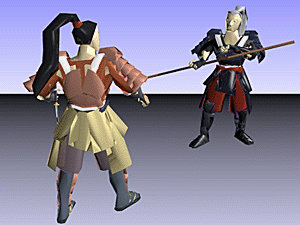
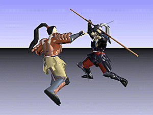
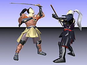
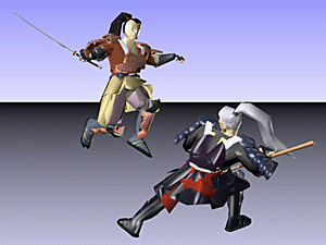
FBX 'Samurai' skinned mesh (with skeleton) model imported, animated & rendered in Okino's NuGraf. Model courtesy of Autodesk.
Click on any image to view a Windows Media 640x480 animation (2.3MB download).
Based on our direct customer experience, our long and focused development, and on the feedback we have provided the animation companies to help correct bugs and problems in their mesh skinning code, we believe we have the best, most refined and most technically advanced skinning conversion systems presently on the market. This is especially true if you need to convert skeletons and skinned meshes between 3ds max (Physique or SkinMod), CINEMA-4D, LightWave, Softimage and Maya; these five programs are particularly not compatible due to bone re-alignment differences, issues with Biped off-axis scaling and 'missing' bind poses from Maya. Our skinning system is also well known for being able to fix incorrectly converted skeletons & skinned mesh conversions created from other free and non-free programs: all you need to do is export to the Okino .bdf file format from 3ds Max or Maya, then re-import the file again - the Okino "Arctic" toolkit will compensate for inherent problems in the conversion process. If you perceive any problems in our skinning conversion system, which rarely if ever occur, then just email us and we'll explain what you are seeing.
Since the concept of mesh skinning is rather straightforward we initially thought that skeleton and skinning data conversion would be a simple matter to develop, but several years after the fact we can say this is not always the case; all sorts of issues can crop up during conversion of such data (that other converters didn't seem to address), such as:
- Propagating "skewing" or "off axis" scaling data in a 3ds max hierarchy down it's skeleton tree before export (a classic problem with 3ds max hierarchies),
- Re-aligning Maya "joints" for use in 3ds max as "bones" by combining and then resampling the animation curves on the skeleton nodes (this unique Okino processing option in our 3ds max plug-ins can even be used to fix up bad conversions made by other converters),
- Converting between the less common method of having the skeleton beneath a mesh (as used by LightWave) to the more typical method of skeletons and meshes being distinct from each other.
- Converting from implicit skin weight formulas (such as in LightWave) to explicit skin weight values, as used by all related 3D file formats.
- Or even computing "sane" sizes & alignments of Maya joint-based skeletons going into 3ds max bone-based skeletons.
For DirectX, Okino has had the industry accepted .X standard exporter implementation since 1997. The .X file format did not change until DirectX 8.1 came along, which added support for real time mesh deformation via smooth skinning techniques, as well as vertex duplication lists. Okino has expanded both its .X importer and exporter to handle mesh skinning and vertex duplication lists, as well as being able to import the new "matrix animation" data representation. As we learned in the deep past, the simplest file formats cause the most trouble to develop, and this is directly applicable to the .X file converters; to allow for care free export of skinned meshes we added the ability to output the mesh data after the skeleton has been output (for cases where a mesh might be located inside a skeleton hierarchy) and automatic creation of extra dummy bones in cases where the vertex weights don't add up to 1.0 on a mesh (DirectX doesn't like that case).
Skeletons in a 3D character animation have a direct correlation to a human skeleton: they consist of articulated joints and bones, and they can be used as a controlling mechanism to deform attached mesh data via "skinning". The skeleton is actually just composed of "null nodes" in 3D space (or "dummy nodes" or "grouping nodes" as they are also often called). Parenting the null nodes together creates an explicit hierarchy, and the transformations on the null nodes define the rotation and offset of each null node from its parent null node. The location of each null node coincides with a "joint" and the distance between two child-parent null nodes defines the length of the bone.
Some 3D programs are "joint based" and others "bones based". Maya and Okino's PolyTrans are "joint based" which means that the bone is visualized implicitly between two joint nodes (two null nodes). Thus, you always need at least two joints to define a bone. Other programs, such as 3ds max and LightWave, are "bone based" which means that a bone is visualized based on a starting location, direction and bone length (a child joint node is not necessary in these programs for a bone to become visible).
Inside Okino's stand-alone software (PolyTrans and NuGraf) skeletons are visualized as a sphere centered at each joint, with a trapezoidal bone connecting the spheres. This is exemplified in the following figure:
"Skinning" is a popular method of performing real time deformation of polygon meshes by way of associated bones/joints of an articulated skeleton. "Skinning" is the process of binding a skeleton to a single mesh object, and skinning deformation is the process of deforming the mesh as the skeleton is animated or moved. As the skeleton of bones is moved/animated, a matrix assocation with the vertices of the mesh causes them to deform in a weighted manner. Skinning is a popular method for doing deformations of characters and objects in many 3D games.
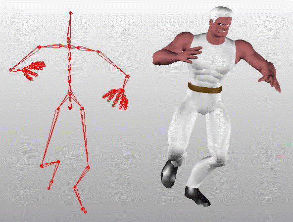
The figure below shows the basic components of skinning, that is the single skin mesh on the right side and the skeleton of bones on the left side. skinning2.gif Left: the Single Skin Mesh. Right: The Skeleton of Bones/Joints. ``Rock'' model from the Autodesk Character Studio CD. Copyright (c) Autodesk.
Okino's PolyTrans and NuGraf software have a nice implementation of mesh deformation via weighted joints, or in other words "smooth skinning". It was created as a pipeline to import, retain, playback, query, optimize and re-export skinned data between the major character animation file formats and animation packages.
Skinning works on the principle of moving one or more "deformer" gizmos which in turn tug on specific vertices of a mesh object in a weighted manner to cause it to deform locally. It is common to have multiple deformer objects assigned to a single vertex, each with a share of the overall deforming "strength", but all which add up to a strength of 1.0.
The traditional character animation system uses a single skin mesh object (ie: an entire human body made from one mesh object) and an associated skeleton. The skeleton is defined simply as a hierarchy of NULL nodes; in some animation systems the skeleton's NULL nodes are visualized as bones (3ds Max, CINEMA-4D, LightWave) which have a source location and direciton, while in other animation systems they are visulized as connected joints+bones (Maya, Okino) which are simply spheres connecting one skeleton node center to the next skeleton node center. The skeleton acts as the deformer to the mesh object which is the deformee. This is illustrated in the figure below which is a skeleton on the left side deforming a single skin mesh in realtime on the rightside; as the bones are moved they deform the mesh object:
Skeleton Causing Deformation of a Single Skin MeshSkinning creation in an authoring package proceeds by selecting a bone/joint and assigning it as a deformer to one or more vertices of a mesh object. A weight value is associated with this vertex/bone assignment. A value of 0.0 means that no tugging will be done while a value of 1.0 will have the bone perform a full tugging on the vertex. In many cases there will be multiple bones associated with a single vertex (so that multiple parts of the skeleton manipulate localized areas of the mesh), in which case all of the weights associated with a single vertex must be "normalized" and add up to 1.0. Also, as an integral step, when the skeleton is first associated ("bound") with the mesh object a series of "bind pose" matrix snapshots are taken which define where the mesh object and where the skeleton joints were located in worldspace at the moment of binding; these "bind pose" matrices provide a sort of static, fixed coordinate system with which the skinning playback algorithm can detect if a skeleton has become animated/transformed, and thus can use the differentially computed changes in the skeleton positions to equally transform the vertices of the bound mesh object, which is the purest definition of "skinning".
As some terminology, if there is one bone per vertex, and the weight is 1.0 then this is "rigid" skinning, else if there are multiple bones per vertex and the weights are not equal to 1.0 then this is "smooth" skinning.
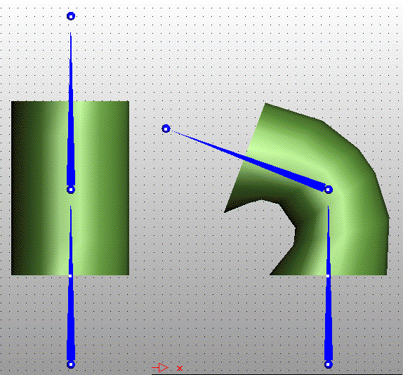
The following figure shows one of the simplest examples of skinning. Here we have a single cylindrical mesh object being deformed by two bones, the bottom one which is static and the top one which is animated. The top cap of the cylinder is only weighted to the top bone while the bottom cap is only weighted with the bottom bone so that the caps don't get skewed unnecessarily; however, the vertices between the top and bottom caps are weighted in different proportions between the top and bottom bone, so that their movement will come about partially from the rotation of the top bone and the static binding location of the bottom bone:
Cylinder Being Deformed by Two Bones
Skeleton Causing Deformation of a Single Skin MeshSkinning is the process of binding a skeleton hierarchy to a single mesh object. This is done by assigning one or more influencing joints (ie: bones) to each vertex of the mesh, each with an associated weighting value. The weight value defines how much a specific bone influences the vertex in the deformation process. NOTE: in general a mesh can be influenced by any other object in the scene as its deformer and not just NULL nodes tagged as skeleton joints; basically any instance, any NULL node instance or any instance tagged as a joint can be used to deform a mesh object (only the NULL node's transformation matrix is needed in the deformation process).
When the mesh is initially bound to the skeleton a "bind pose" world-space snapshot is taken of all transformation matrices of the mesh and skeleton nodes. These bind pose matrices allow any vertex position to be transformed into the local coordinate space of its associated influencing bone, at the time when the mesh and skeleton were in their original undeformed position (the "bind pose", "rest position" or "reference pose"). During realtime playback any movement of the skeleton away from its "bind pose" will cause the mesh to deform accordingly.
If a skeleton and mesh have been imported and bound together with skinning weights, then most probably the bind pose matrices have been defined and set as well. These matrices define the world-space location of the mesh object and its related skeleton bones/joints at the time of binding. Normally in the PolyTrans/NuGraf user interface you will see the mesh deformed under the influence of the skeleton's current pose (unless skinning is globally disabled). If you wish to revert the skeleton and mesh back to their poses at the time of initial binding, with no deformations applied, then you need to "Go to Bind Pose" on the mesh instance and every bone/joint instance. The final result will look like the following image (initial bind pose often has the arms stretched out and palms of the hands downward):
Model Forced into "Bind Pose"
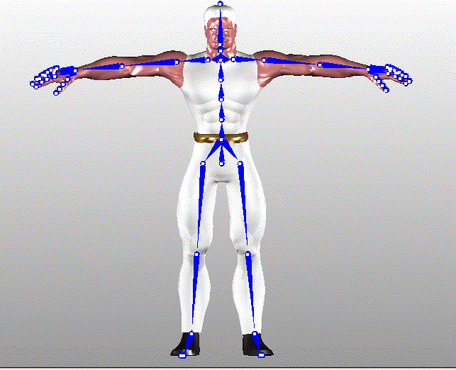
The "bind pose" is often the most confusing aspect of learning to program the skinnig API yet the absolute most important concept to understand. The "bind pose" is the pose of the mesh object, the skeleton and their relative offsets at the moment the skeleton is bound to the mesh object and before any deformations begin to occur. This pose will often look like that shown in the figure above with the arms stretched out and level with the shoulders, and with the skeleton aligned with the limbs of the mesh object:
At this very moment, when the skeleton bones get bound to the mesh (via the bone/vertex assignments with corresponding weight values), a "snapshot" matrix called the "(Worldspace) Bind Pose Matrix" is taken for every bone/joint and the mesh itself (not to be confused with the local transformation matrix). These are very key and important matrices for skinning. The Bind Pose Matrices are stored in the instance definitions defining the mesh object and the skeleton bones/joints (bones/joints in the NuGraf toolkit are just NULL nodes, or empty instances as they are often called). The Bind Pose Matrices define the original world-space location of the mesh and bones/joints at the time of binding.
How are Bind Pose Matrices used during skinning deformation? This is the key point to comprehend: the matrices allow a raw vertex of the mesh (in local coordinates) to be transformed into world-space and then to each bone's local coordinate space, after which each bone's animation can be applied to the vertex in question (under the influence of the weighting value). The mesh's bind pose takes the vertex from local space to world-space, and then each bone's inverse bind pose takes the mesh vertex from world-space to the local space of that bone. Once in the bone's local space, the bone's current animated transformation matrix is used to transform (deform) the vertex's location. After all the bone influences have been taken into account, the vertex ends up in world-space in its final deformed location. In other words, these bind pose matrices relate the location of a vertex in its local mesh space to the same location of the vertex relative to each bones' local coordinate systems. Once this relation is known, via the bind pose matrices, it is easy to deform the mesh vertices by animating the bones.
All you need to keep in mind is that the mesh's Bind Pose Matrix takes its vertices into world-space, to the location at the time of binding, and each bones' Bind Pose Matrix takes the bones from local space to world-space at the time of binding.