| You are here: Home » Import CAD Formats » NGRAIN's 3KO Solutions |
Support: 905-672-9328 Copyright © 2026 Okino Toronto, Ontario, Canada. |

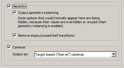
Output Hierarchy
If this option is enabled (checkmarked) then the hierarchical relationship of objects in the scene will be exported using nested CINEMA-4D nodes. If this option is disabled then no hierarchy will be output and all mesh objects will be exported in flattened world-space coordinates.
Output geometry instancing (use instancing to reduce file size)
If this checkbox is checkmarked then the mechanism of "instancing" will be used to try and keep the size of the CINEMA-4D file as small as possible. For example, if the source scene has 1000 bolts all derived from the same mesh primitive data, and the 1000 items have been placed in the Okino scene graph via "instancing" then during export to CINEMA-4D only a single copy of the geometry mesh data will be exported to CINEMA-4D, but with 1000 virtual copies made of it. These virtual copy instances merely act as indexes to the original mesh primitive data instead of being full copies, which can significantly reduce the size of the final output.
Note: CINEMA-4D does have one key setback with its concept of instancing. Any instance which uses a different material from another instance will require that the base geometry be duplicated. In other words, CINEMA-4D does not allow for the instance definition to define & override its own material - rather, the materials are associated only with the base geometry and thus cannot be overridden on an instance-by-instance basis. Thus, 500 red colored bolts and 500 blue colored bolts will require 2 materials (red and blue), 2 duplicated copies of the base geometry (assigned to the red and blue materials), and 1000 instance nodes.
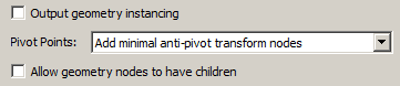
If this checkbox is disabled then unique and explicit copies of mesh data will be output to the CINEMA-4D file regardless of whether each copy is exactly the same as previous copies already exported.
Remove empty/unused leaf transforms (empty grouping nodes)
If an exported NULL/grouping node has no children, is not a joint of a bone hierarchy and has no animation on it, then such useless grouping/NULL nodes are deleted during the export process if this checkbox is enabled..
If this option is disabled then such useless grouping/NULL nodes are retained during the export process into CINEMA-4D and not deleted. You will want to disable this checkbox if you are exporting a file of NULL nodes and you wish all of them to be exported without pruning.
When the "Output geometry instancing" is disabled, the dialog box changes to look as follows:
Pivot Points
Pivot points are a fundamental component of an animation system. In the realm of the Okino animation system 'pivot points' define a local 3D coordinate system in the space of an object about which the scale, rotation and translation animation function curves will be applied. The pivot point in Okino's scene graph is defined by a 3D point in space and a local coordinate system defined by 3 orthogonal XYZ axes; the pivot point is itself defined relative to the local coordinate system of the underlying mesh or geometry data.
For example, the virtual pivot point and its orientation axes allow a robot arm to properly rotate around its 'elbow' joint instead of some other awkward point of the object. Any such animation placed on the robot arm will then naturally occur relative to this 'elbow joint'.
A basic problem is that not all destination animation programs have the same concept of "pivot points" as with a source animation program. Some programs are more complex, some much simpler. The following options control how Okino software performs this 'mapping'.
First, some rules need to be defined for the following explanations. "Pivot point processing" only needs to be done under these circumstances for the two Minimal modes:
1) The pivot point 4x4 matrix has a non-zero origin or non-aligned orientation axis. In other words, it has something 'interesting' in it, or
2) The instance has animated channels associated with it, or
3) The (static) transformation matrix associated with an instance has "off-axis" scaling within it. Off-axis scaling is where rotation comes before scaling, which is basically an illegal or poorly supported situation for most 3D programs.
For a 'grouping folder' (an Okino 'empty instance'), which is deemed to have a valid pivot point matrix, a new child 'anti-pivot' node is added to the exported hierarchy tree - the child node is assigned the inverse pivot matrix and the original parent transform node gets the animation data. This properly applies the anti-pivot effect to the subsequent children in the tree.
The following options specify how the Okino pivot point information is exported for instance-geometry nodes:
Embed pivots in *all* geometry data
Logic - regardless of the '3 rules' explained above, this processing mode will be invoked on ALL instance-geometry nodes if any of them have a non-identity pivot matrix.
The inverse pivot matrix is multiplied into the raw mesh geometry vertices. In other words, the messy 'pivot point' problem is made to disappear by having its 4x4 matrix physically multiplied into the mesh geometry vertices.
Embed minimal pivots in geometry data
Logic - same as above except that the processing mode will only be invoked when one of the '3 rules' explained above are valid. This leads to a cleaner conversion.
Output *all* anti-pivot transform nodes
Logic - regardless of the '3 rules' explained above, this processing mode will be invoked on ALL instance-geometry nodes if any of them have a non-identity pivot matrix.
A new "anti-pivot" dummy node is introduced into the exported hierarchy tree, between the mesh geometry object and the parent transform node (which has the animation on it). The inverse of the Okino pivot point matrix is assigned to the transformation matrix of this new anti-pivot dummy node. This new anti-pivot node acts to 'pivot-in' the geometry vertices prior to the animation data being applied to the geometry.
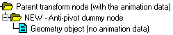
Thus, this mode 'splices in' the pivot point matrix into the destination hierarchy tree as a new transformation node rather than to multiply the pivot point matrix into the raw mesh geometry, as with the other modes.
Add minimal anti-pivot transform nodes
Logic - same as above except that the processing mode will only be invoked when one of the '3 rules' explained above are valid.
This is the default option since (1) it results in the fewest changes to the output hierarchy tree and (2) it does not physically affect the mesh geometry coordinate data.
Ignore all pivot point data (can cause problems)
This option prevents pivot point information from being output to the CINEMA-4D file. Normally you would never want to enable this option.
Allow geometry nodes to have children
This option allows a form of "hierarchy compression of scene nodes" or "visual cleanup of a hierarchy". It is disabled by default.
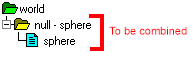
In simple terms, if an Okino 'Yellow grouping folder' contains a single mesh geometry object then these two nodes will be compressed together and output to the CINEMA-4D file as a single node. Otherwise, the two nodes will be output separately.
For this to occur, some conditions need to apply:
- The parent node needs to be a 'grouping folder' (empty instance in Okino lingo).
- The parent node cannot be a skeleton joint.
- The parent and child nodes cannot have different materials assigned to them.
- The bind pose matrix for skinning needs to be the same on both nodes.
- The names of the parent and child geometry nodes must be 'similar', as explained further below.
- The child geometry node cannot have mesh skinning weights.
Also, the parent node needs to be named in a specific manner to that of the child geometry node. If we were to assume that the child geometry node was named 'example' then the parent grouping node needs to be named in one of the following ways:
null - example example - mesh example - splineshape exampleShapeThe logic behind some of these rules follow from how 3ds Max and Maya name their parent transform & child geometry nodes. That carries over to this hierarchy optimizer in the CINEMA-4D exporter.
Output Cameras
If this checkbox is checkmarked then all perspective and orthographic cameras will be output to the CINEMA-4D file as either targeted (look-from, look-at) or 'free' cameras. Near and far clipping plane values will also be output.
Simple info note: CINEMA-4D uses FOV (field-of-view) to define the width of the perspective projection plane whereas it uses ZOOM to define the width of an orthographic projection plane.
Output As:
Target-based ('look-at') cameras
Choosing this radio button will cause all cameras to be created as CINEMA-4D "Targeted cameras". Targeted cameras use 2 nodes, one for the "Look-From" location and one for the "Look-At" location. CINEMA-4D will always orient the targeted camera so that the "Up" vector points straight up (as compared to Okino software, and other 3D programs, which allow a third, explicit "Up vector" to be orientated in any direction).
Two nodes will be output to the CINEMA-4D hierarchy, one with the same name as the Okino camera definition and the other named with a '.Target' appended to it.
Rotation-based ('free') cameras
Choosing this radio button will cause all cameras to be created as CINEMA-4D "free cameras". Free cameras use a single node which defines the Look-From location and an arbitrary rotation matrix to orient the camera. The Okino camera 'roll' value will be output as the CINEMA-4D 'bank' angle in radians.
Free cameras do not exhibit 'Euler gimbal lock' when the camera 'goes over the poles', that can otherwise happen with targeted cameras.
Simple info note: CINEMA-4D's free-cameras point down the positive-Z axis when they have zero-rotation. However, CINEMA-4D's positive-Z axis is equivalent to Okino's negative-Z axis.