

| You are here: Home » Import CAD Formats » NGRAIN's 3KO Solutions |
Support: 905-672-9328 Copyright © 2026 Okino Toronto, Ontario, Canada. |
|
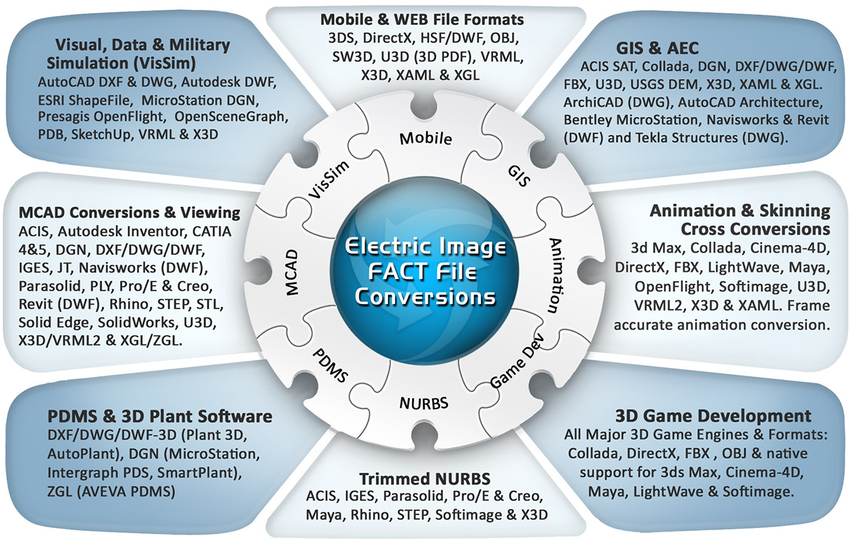
Okino's FACT conversion system intelligently and robustly creates native .fact files (for use within the world famous Electric Image Animation System (EIAS) and the renowned modeler Form/Z) from almost every 3D CAD, DCC, animation and VisSim program.
Click for larger image.
Note: some conversion paths shown in this image are uni-directional only.You may also want to consider using Okino's FBX exporter to convert scenes over to EIAS, including skinning and animation data which is not possible via the FACT file format. It is also possible to convert scenes with texture maps into EIAS using the Wavefront OBJ file format but OBJ does not support hierarchy, lights, cameras, animation, meta data or mesh skinning.
Please also refer to the full featured FACT import converter.
- The only FACT converter which exists within a professional 3D conversion program. Okino was originally approached
by a movie production company to help them integrate the Electric Image Animation System (EIAS)
into their end-to-end 3D pipeline. From that request came 3 years of development work, as implementing the complex
FACT file format was found to be one of the more complex conversion development projects undertaken.
- Exports polygonal geometry (or NURBS converted to polygons) with associated vertex normals, uv texture coordinates, vertex colors and tangent vectors,
- Export of complex FACT hierarchy, including the preservation of linkage information and child/parent transformation information. Pivot points are properly exported as linkage information.
- Complex material information is exported:
- Diffuse, specular, ambient and luminance colors.
- Diffuse, specular, ambient and luminance shading coefficients.
- Transparency, reflectivity, index of refraction and diffuse bias.
- Converts between Electric Image's left handed coordinate system and right handed coordinate system.
- The ability to selectively export
- Vertex texture coordinates
- Object hierarchy
- Texture bitmap references
- Materials
- All inherited attributes such as position, rotation and scale are properly handled.
- Outputs texture UV coordinates as well as various forms of texture projections (where applicable). Since the size of texture projections depend upon the bitmap resolution of their associated texture maps, this exporter also locates and opens up the texture images to obtain their resolutions.
- The converter can scale and translate geometry during export
- Some complex material properties are not handled, such as:
- Edge attributes (edge transparency, edge maps)
- Reflection Color
- Glow (although luminance is supported)
- Silhouettes
- Dissolves
- Edge attributes (edge transparency, edge maps)
- UV coordinates can be imported/exported but the current FACT format has no way of enabling the use of this information during texturing. It is possible to work around this manually. (Refer to the explanation later in this document.) The reasons for this is that UV's are enabled within the project file and not within the FACT (object) file.
- Lights and cameras cannot be exported because they are stored in the Electric Image project file instead of FACT files.
Converting between texture projections is one of the most difficult tasks this exporter performs. Although Electric Image and NuGraf/Polytrans support the same types of texture projections, the way they are represented are quite different. In NuGraf/Polytrans, the projections are represented by a series of vectors which define key points on the texture projections. For example, for a cylindrical projection three vectors are used. One indicates the middle of the top face of the cylinder, and the other vectors indicate two points on the cylinders base. In Electric Image each projection type has a slightly different format. For a cylinder information such as height, radius, and a series of rotations are used to determine how to place a texture projection. Other projections, such as the flat projection, store information about an object's bounding box and the resolution of the bitmap!
The converter first takes the vectors from NuGraf/PolyTrans and creates a coordinate system. It also uses the magnitude of these vectors to determine the width, height and depth of the texture projection. It then calculates rotations and translations from a matrix representing the coordinate system of the projection. Using all of this information plus information about the bitmap being applied, the exporter is able to convert between these different representations of the same projection system.
Due to the nature of the FACT format, it is difficult to handle UV coordinates. The file format itself allows the output of UV information but there is no way for the file to specify that mesh objects should use the UV data for texture mapping by default (in other words, Electric Image will not use the UV texture mapping data by default, even though it is within the FACT file). This the exporter will export an object with texture UV's and also a default spherical texture projection associated with the textures.
Consider the following model to be exported from PolyTrans/NuGraf. It is a simple polygon cube with a texture map applied to it using uv coordinates. This is an image of the cube as rendered with Okino's NuGraf software.
After being imported into Electric Image the cube looks like the image shown on the right side (using a "flat" texture projection). It looks incorrect because Electric Image is using a flat (planar) texture projection by default and not the proper UV texture coordinates found within the FACT file.
Now, the FACT exporter does indeed output proper UV texture coordinates. However, Electric Image does not use these by default. To have Electric Image use the UV texture coordinates exported to the FACT file double click on the cube object within the Electric Image user interface.
This action will bring up a dialog for the cube object. Now click on the "Shading" tab. In the lower right portion of this panel there should be an option entitled "Use UV Space". Select this option to enable UV coordinates for texturing. This process must be repeated for each texture mapped object in the scene.
If you were to re-render the cube within Electric Image then the following image (shown on the right) would appear. This is the same mapping as the original box we exported and proves that UV texture coordinates can be successfully exported to the FACT file format and to Electric Image.
The following information explains the various options on the dialog box:
Output MacBinary Header
If this checkbox is enabled (checkmarked) then a MacBinary header will be added to the front of the exported FACT file. This is necessary if the file is written on a PC machine but read into Electric Image on an old Macintosh computer. The type will be set to FACT and the creator will be set to EIAM.Mirror Scene in XY Plane (flip Z)
If this checkbox is enabled then all Z coordinates will be negated before being output to the FACT file. This is necessary for proper coordinate system conversion.Center All Geometry At the Origin
If this checkbox is enabled (checkmarked) then all the geometry data will be positioned so that it is centered about the origin. If disabled then the geometry will not be repositioned. The default is disabled.Make Geometry Sit on the Z=0 Horizontal Plane
If this checkbox is enabled (checkmarked) then the geometry will be repositioned so that it is sitting flush with the top of the Z plane (the horizontal plane). The default is disabled.Scale Geometry to be no Large Than...
This option allows the geometry data to be automatically rescaled if it is too large. If set to 'Do not scale the geometry' then no scaling will be done. If set to '1x1x1 units' then all the objects will be scaled smaller should they exceed 1x1x1 units in total size. Likewise for the '2x2x2 units' option. If set to 'User defined maximum size' then the maximum size of all the objects can be set using the type-in numeric box.Although not quite the same, if the option is set to 'Use Absolute Scaling Factor' then all objects exported to the FACT file will be scaled absolutely by the user specified value. Thus, if you set the type-in value to 0.25 then all objects will be made 4 times smaller and if the value if set to 4 then all objects will be scaled 4 times larger. This is useful is you are converting a variety of different models to FACT format and you want them all uniformly scaled with the same scaling factor.
Output Enables
The following options control what is sent to the FACT file:Hierarchy Information
If this checkbox is enabled (checkmarked, which is the default) then hierarchy information will be output to the file, else the geometry will be output with no hierarchy.Texture (u,v) Coordinates
If this checkbox is enabled (checkmarked, which is the default) then (u,v) texture coordinates will be output to the file, else the (u,v) texture coordinates will be set to (0,0).Texture Bitmap References
If this checkbox is enabled (checkmarked, which is the default) then references to bitmap textures will be output along with the material definitions in the FACT file.Materials
If this checkbox is enabled (checkmarked, which is the default) then materials will be output to the file.
Please refer to the FACT import converter documentation for complete documentation on which FACT file format chunks are supported.