| You are here: Home » Import CAD Formats » NGRAIN's 3KO Solutions |
|
This geometry export converter writes out the scene database as a C code program in the Open GL scene description language. The resulting program can then be compiled and used to draw the 3d database directly using OpenGL.
The database is output as a series of polygons with vertex positions, normals, colors and texture coordinates. In addition, the surface definitions (materials) associated with each polygon is used to set up the OpenGL shading parameters.
Please note that each object is output as a separate C code function in the resulting file.
- Each geometry object is output to the OpenGL C file as its own function definition (ie: "Sphere#1" is enclosed in a function like: Sphere#1()).
- Mesh data can be output as unrolled loops or "vertex arrays" for high performance output. Vertex positions, vertex normals, uv texture coordinates and vertex colors can all be output.
- The Okino triangle stripper algorithm is used to take any form of geometry data and turn it into optimized tri-strips for use by the OpenGL tri-strip data type. This reduces the number of vertices that have to be transformed by OpenGL.
- Options to automatically have the scene rescaled to a user specified maximum size or some absolute size, as well as options to center the geometry at the origin and/or make the geometry sit on the Z=0 horizontal plane. This benefits OpenGL rendering quality in cases where the extents of the scene cause the OpenGL clipping planes to be spaced too far apart; scaling the scene smaller allows the clipping planes to be kept closer together and thus reduce rendering anomalies (due to limited precision in the Z buffer).
- A Microsoft Visual C++ .dsp/.dsw project and workspace are output in addition to the frame work to an OpenGL application program. Thus, you get the base OpenGL C program to represent your 3D scene (geometry, lights, camera, textures, etc). as well as an OpenGL C program to display the 3D scene in a Microsoft Windows window.
- Removal of redundant coordinates for optimized mesh output.
- Control of color output by weighting of the shading coefficients which are carried over from the imported file format.
- Automatic bitmap conversion from all supported 2D bitmap file formats into whatever you require in your OpenGL C program, with .bmp being the default.
- If an object has multiple materials assigned to it, and tri-strips are used, then the tri-stripper will sort the polygons by material reference. This may, in some cases, reduce the number of times that a OpenGL material definition has to be context switched.
- Concave polygons will be triangulated prior to output.
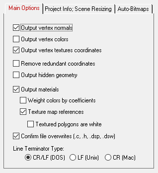
This panel mainly controls how the mesh data will output to the OpenGL C program file as well how the materials will be handled.

Output Vertex Normals
If this option is enabled (checkmarked) then vertex normals will be output along with each polygon vertex using the glNormal3f() function. If a polygon does not have any vertex normals associated with its vertices then nothing will be output.Output Vertex Colors
If this option is enabled (checkmarked) then vertex colors (r/g/b values) will be output along with each polygon vertex using the glColor3f() function. If a polygon does not have any colors associated with its vertices then the default surface (material) color will be output before the polygons are specified.Output Vertex Texture Coordinates
If this option is enabled (checkmarked) then texture mapping coordinates (u/v coordinates) will be output along with each polygon using the glTexCoords() function.Remove Redundant Coordinates
If this option is enabled then the vertex coordinate, normal coordinate, uv texture coordinate and vertex color arrays will be optimized prior to output by removing redundant (duplicated values) to a tolerance of 1e-5.Output Hidden Geometry
If this option is enabled then any geometry tagged as being "hidden" in the internal PolyTrans database will be output to the OpenGL .C file as unhidden geometry. If this option is disabled then any geometry tagged as being hidden will be ignored and not output to the OpenGL .C file.Output Materials
If this option is enabled (checkmarked) then surface shading parameters will be output along with the polygons as well as the basic vertex colors. The shading parameters set up Open GL's shading mechanism for the diffuse color, the specular color and the Phong shininess value. These values are taken from the current surface definition (material) that is associated with the current polygon being output. Note that the shading parameters will only be output when they change from the previous values that have been output (for optimized drawing).Weight Colors by Coefficients
Each material in PolyTrans has a color and an associated shading coefficient. For example, you might have a diffuse color of (1,1,1) and a shading coefficient of 0.35, which means that only 35% of the 100% bright diffuse color will be used in the final shading calculations. If this option is enabled then the shading coefficient will be multiplied into the base color prior to output to OpenGL, else just the base color will be output unmodified. In general it is more accurate to enable this option.Output Texture Map References
If this option is enabled, which is the default, then texture map filename references will be output to the OpenGL C code. Otherwise, if the option is disabled then no texture map filename references will be output.Set Textured Polygons as White
If any polygons are found to be associated with a texture map, and this option is enabled, then the diffuse color for the materials assigned to those polygons will be set to white. In OpenGL it uses a multiplicative effect when displaying textures, such that the underlying diffuse color gets multiplied into the texture color, whereas in most rendering programs the texture color is additive or replaces the underlying diffuse color. Thus, if your source materials are dark or black, then enable this option to allow the texture maps to not become black.Confirm File Overwrites (.c, .h, .dsp, .dsw)
If this option is enabled then any potential overwrites of the sample_display.c, sample_display.dsw or sample_display.dsp files will first be confirmed with yourself. Disabling this option will cause these files to be overwritten all the time.Line Terminator Type
This common option selects which line terminator is to be used for the ASCII output file:
- Files destined for DOS/PC machines should use CR/LF,
- Files for UNIX machines should use LF, and
- Files for Macintosh machines should use CR.
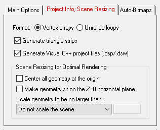
This panel controls "how much" content is output to the .C program file, in what manner, and whether a Microsoft Visual C++ project/workspace set of files are output. This panel also allows the scene contents to be re-scaled prior to export.

Format: Vertex Arrays or Unrolled Loops
These selects whether the geometry is to be output in highly efficient vertex arrays or as unrolled loops. The following are extracts of a sphere exported to a .C file as vertex arrays or unrolled loops. Vertex arrays are preferred over unrolled loops.void Sphere_as_unrolled_loop() { // Polygon # 0 glBegin( GL_TRIANGLE_STRIP ); glNormal3f( -0.250000f, -0.866025f, 0.433013f ); glTexCoord2f( 0.666667f, 0.166667f ); glVertex3f( -0.500000f, 0.267949f, 0.866025f ); ... glNormal3f( 0.000000f, -1.00000f, 0.000000f ); glTexCoord2f( 0.750000f, 0.000000f ); glVertex3f( 0.000000f, 0.000000f, 0.000000f ); glEnd(); }Sphere_as_Vertex_Arrays() { static GLfloat VertexData[] = { 1.93185f, 2.51764f, 0.000000f, 1.93185f, 2.51764f, 0.000000f, 2.00000f, 2.00000f, 0.000000f, 2.00000f, 2.00000f, 0.000000f }; static GLfloat NormalData[] = { 0.965926f, 0.258819f, 0.000000f, 0.965926f, 0.258819f, 0.000000f, 1.00000f, 6.12303e-017f, 0.000000f, 1.00000f, 6.12303e-017f, 0.000000f }; static GLfloat TexCoordData[] = { 1.00000f, 0.583333f, 0.000000f, 0.583333f, 1.00000f, 0.500000f, 0.000000f, 0.500000f }; static GLint Indices[] = { 40, 50, 72, 84, 112, 118, 130, 118, 138, 270, 259, 270, 236, 232, 154, 232, 260, 269, 291, 156, 230, 235, 269 }; glEnableClientState( GL_TEXTURE_COORD_ARRAY ); glTexCoordPointer( 2, GL_FLOAT, 0, TexCoordData ); glEnableClientState( GL_NORMAL_ARRAY ); glNormalPointer( GL_FLOAT, 0, NormalData ); glEnableClientState( GL_VERTEX_ARRAY ); glVertexPointer( 3, GL_FLOAT, 0, VertexData ); glDrawElements( GL_TRIANGLE_STRIP, 43, GL_UNSIGNED_INT, &Indices[29] ); glDrawElements( GL_TRIANGLES, 3, GL_UNSIGNED_INT, &Indices[97] ); glDrawElements( GL_TRIANGLE_STRIP, 6, GL_UNSIGNED_INT, &Indices[621] ); }Generate Triangle Strips
If this option is enabled then the exporter will attempt to create the longest possible triangle strips from unsorted source polygon data. This can be seen in the example C code above where the sphere was turned into a combination of triangles and triangle lists. Triangle strips are more efficient because fewer vertex attributes have to be output (those which are shared between triangles are not sent to the OpenGL pipeline more than once).Generate Visual C++ Project Files (.dsp/.dsw)
Enabling this option will create 3 files, sample_display.c, sample_display.dsw and sample_display.dsp. This forms a bare bones example C container program to load up the exported .C geometry file (using GLUT for display) and the corresponding Visual C++ workspace files. Just load up the .dsw file into Visual C++ and compile.Scene Resizing for Optimal Rendering
From experience, OpenGL often shows rendering "anomalies" when the scene is too large compared to the resolution of the Z buffer. When this case occurs the quality of the hidden surfaces will degrade. The solution is to keep the near and far clipping planes close to the bounds of the scene, and keep the size of the overall scene smaller than the maximum dynamic range of the Z buffer. The following options will provide you with complete freedom to have the scene extents scaled to a user settable maximum or absolute size, thus providing a means to control rendering problems of large scenes.Center All Geometry At the Origin
If this checkbox is enabled (checkmarked) then all the geometry data will be positioned so that it is centered about the origin. If disabled then the geometry will not be repositioned. The default is disabled.Make Geometry Sit on the Z=0 Horizontal Plane
If this checkbox is enabled (checkmarked) then the geometry will be repositioned so that it is sitting flush with the top of the Z plane (the horizontal plane). The default is disabled.Scale Geometry to be no Large Than...
This option allows the geometry data to be automatically rescaled if it is too large. If set to 'Do not scale the geometry' then no scaling will be done. If set to '1x1x1 units' then all the objects will be scaled smaller should they exceed 1x1x1 units in total size. Likewise for the '2x2x2 units' option. If set to 'User defined maximum size' then the maximum size of all the objects can be set using the type-in numeric box. The default is ' Do not scale the geometry'.Although not quite the same, if the option is set to "Use Absolute Scaling Factor" then all objects exported to the OpenGL file will be scaled absolutely by the user specified value. Thus, if you set the type-in value to 0.25 then all objects will be made 4 times smaller and if the value if set to 4 then all objects will be scaled 4 times larger. This is useful is you are converting a variety of different models to OpenGL format and you want them all uniformly scaled with the same scaling factor.
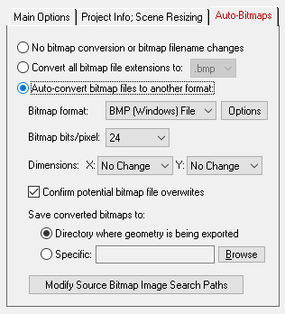
This dialog box allows referenced bitmaps (of the internal 3D scene database) to be automatically converted to other 2d bitmap formats during the export process. The three options available are:
- Do not modify the bitmap filename reference and do not perform any bitmap conversion.
- Modify the extension of the bitmap filename to a bitmap format (chosen from a drop-down list) but do not perform any bitmap conversion. This option is useful if you have (1) either performed the bitmap conversions in a previous export process or (2) you wish to use an external program (such as PhotoShop) to perform the bitmap conversions.
- Perform bitmap conversion and change the file extension of the bitmap. For example, if your original 3D scene data referenced JPEG bitmaps, but you want the exported OpenGL file to reference BMP bitmaps, then this option can be used to automatically convert the JPEG files to BMP and change all bitmap references to the new BMP files.

No Bitmap Conversion or Bitmap Filename Changes (Radio Button)
If this radio button is chosen then any bitmap reference exported into the OpenGL file will not be changed, its filename extension won’t be changed, the path to the bitmap will not be changed and no bitmap conversion will be done.Convert all Bitmap File References To... (Radio Button)
Rather than convert referenced bitmap images to another file format this radio button (when selected) simply changes all the file extensions on bitmap files to a specific type. For example, if set to “BMP” then all bitmap filenames exported to the OpenGL file will be changed so that their file extensions end in “.bmp”. This is a useful option is you already have all of the referenced texture maps converted to the desired file format (either from a previous invocation of this export converter or by using a batch bitmap conversion program).Auto-Convert Bitmap Files to Another Format (Radio Button)
If this radio button is selected then all 2d bitmap textures which are currently defined and referenced by the internal NuGraf/PolyTrans database scene will be automatically tagged then converted to a new user-specified 2d bitmap file format during export. The desired format is chosen using the Bitmap File Format combo box. If the texture(s) cannot be found in the location specified by the pathname prepended to the input texture filename then the export converter will search for the texture(s) in all directories specified in the ‘Default Search Path’ and the ‘Texture Bitmaps Search Path’ file search paths (these can be modified by choosing the ‘Preferences/Configure File Search Paths’ menu item.Bitmap File Format (Combo Box)
This combo box lists the destination bitmap file format. The default is BMP format.
No Change = Do not change the X or Y size Closest = Use the next highest power-of-2 size 2, 4, 8, ... 256, 512 = Choose a specific size for the X or Y dimension Save Converted Bitmaps To...
These radio buttons determine where the new bitmap file will be written to.
Directory Where Geometry Is Being Exported
The new bitmaps will be written to the directory where the OpenGL file is being exported to.Specific + Browse
The new bitmaps will be written to the directory specified by the text box. This directory can be changed by press the ‘Browse’ button.

