| You are here: Home » Import CAD Formats » NGRAIN's 3KO Solutions |

The is one of Okino's key export converters which allows complex scenes to be exported out to the Autodesk Softimage dotXSI model file format, for subsequent loading into the Softimage animation program (or any other program which imports the dotXSI file format). Meshes, trimmed NURBS surfaces, NURBS curves, hierarchy, object/camera/light/material animation, mesh enveloping (skinning), materials, textures, shader trees (dotXSI 3.6), cameras and lights are properly exported, including automatic bitmap conversion.
Please also refer to the corresponding dotXSI import converter.
This dotXSI exporter will run inside any Okino compliant program such as the stand-alone PolyTrans or NuGraf programs, PolyTrans-for-3dsMax or PolyTrans-for-Maya native plug-in systems.
- Support for dotXSI 3.0, 3.5 and 3.6 file format standards. This covers a lot of different territory and templates!
- Polygonal meshes with vertex normals, (u,v) texture coordinates and vertex colors. Explosion of meshes into sub-meshes for dotXSI files where multiple materials are assigned per mesh.
- NURBS trim curves on NURBS surfaces, for dotXSI v3.6 format.
- Independent NURBS curves and curve lists.
- Excellent and robust support for dotXSI "skinned mesh" and skeleton export, which ties into the Okino Arctic toolkit. This allows PolyTrans to cross convert skinned mesh, animation and skeleton data between Softimage,
Maya, 3ds Max, CINEMA 4D, LightWave, U3D, DirectX, COLLADA and FBX file formats, with proper bone re-orientation, off-axis scaling removal, and so forth.
- Lights, cameras and their related parameters.
- Object, camera, light and material animation export, as well as hierarchy processing and export. Okino's Arctic toolkit provides the front-end to the dotXSI animation export system, and thus fully utilizes its "dense matrix" keyframe resampling and reduction algorithms. Arctic is also used to ensure that all Euler animation output is properly done (because Euler animation conversion can be fraught with problems).
- Automatic bitmap conversion for numerous export file formats.
- Material and associated animation export to dotXSI v3.5 "shader trees". This is one of the more complex aspects of this dotXSI exporter:
- Up to seven texture layers can be ouput for each illumination channel (eg, diffuse, ambient, etc).
- Phong and Blinn illumination shaders supported.
- Transparency and reflection can be mapped to textures.
- Texture alpha channel support, including most of Okino's built-in alpha channel sources.
- "Image library" templates (dotXSI 3.6 or newer only)
- Produces optimized shader tree output whereby routing of the shader connections is done with foresight.
- Up to seven texture layers can be ouput for each illumination channel (eg, diffuse, ambient, etc).
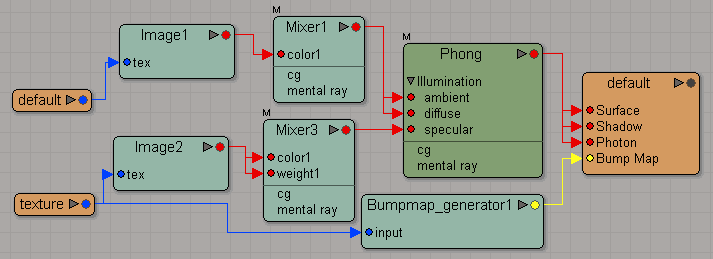
The following images show some typical shader trees created by this exporter to replicate the internal shader system used by the Okino internal database.
(Click image for full resolution version)
- The corresponding Softimage .xsi file import converter.
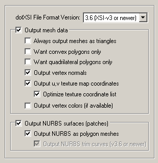
dotXSI File Format Version
This combo box selects which version of the dotXSI file format you desire to export. These version numbers DO NOT relate to the version numbers of the Autodesk Softimage program itself (such as v1.5 or v2.0).If you wish to output the more modern and complex 'XSI_Materials' (which use shader trees) then use dotXSI v3.5 or newer file format.
If you wish to output trim curves for NURBS surfaces, and the "XSI Image Library" template then use dotXSI v3.6 or newer file format.
Output mesh data
If this checkbox is checkmarked then mesh geometry will be exported. This option also controls whether meshed versions of NURBS surfaces or renderable NURBS curves will be output as well.Always output meshes as triangles
Checkmark this checkbox to cause 4 or more sided polygons to become triangulated. This will ensure that all meshes are output as the dotXSI " SI_TriangleList" primitive.Want convex polygons only
Checkmark this checkbox to cause non-convex (concave) polygons to become triangulated. An example of a concave polygons is a star shape.Want quadrilateral polygons only
Checkmark this checkbox to cause 5 or more sided polygons to become triangulatedOutput vertex normals
If this checkbox is checkmarked then vertex normals will be exported along with the mesh geometry. Vertex normals are used by the dotXSI file format to transfer smoothing information about polygonal objects.Output u,v texture map coordinates
If this checkbox is checkmarked then (u,v) vertex texture coordinates will be exported along with the mesh geometry. (u,v) vertex texture coordinates are used to define how the 2D bitmap textures (texture maps) are mapped onto each 3D mesh object.Optimize texture coordinate list
Checkmark this checkbox to have the any duplicated uv texture coordinates removed from its respective list in the mesh object.Output vertex colors (if available)
If this checkbox is checkmarked then all the colors assigned to each and every vertex will be exported along with the mesh geometry. Vertex colors are not often found in 3D object geometry files but rather are often used either in radiosity solution outputs or in 3D game design; typically color is assigned to polygons via material definitions and not singular colors per vertex.Output NURBS surfaces (patches)
If this checkbox is checkmarked then trimmed NURBS surfaces will be exported, either in raw form or as converted polygon meshes.Output NURBS as polygon meshes
If this checkbox is checkmarked then the raw trimmed NURBS will be tessellated into a polygon mesh prior to export. If it remains uncheckmarked then the raw trimmed NURBS data will be exported directly.Output NURBS trim curves
If the above option is disabled (pure NURBS output enabled) then this checkbox determines whether trim curves will be output along with the parent trimmed NURBS surfaces. Trim curves define the outer boundary of a NURBS patch as well as specifying internal trim holes and islands. Trim curves are only output if you have set the file format version to 3.6 or newer. Only Softimage v3.0 or newer will be able to import trim curves.
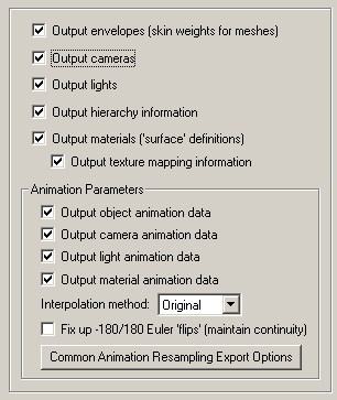
Output Envelopes (Skin Weights for polygon meshes)
"Mesh skinning" (or enveloping as it is known within Softimage) is the process of deforming a single skin mesh with a skeleton (in the dotXSI file the skeleton is represented by the NULL nodes' matrices which define the pivot point and orientation of each invisible bone). The contribution of each bone of the skeleton to the deformation of a vertex in the mesh is controlled by vertex weights. If this option is enabled then a mesh will be bound to one of more objects in the dotXSI file (which represent the bones or joints of the skeleton) via transformation matrices and weight values. This option is only valid if the source data has at least one mesh object bound to any number of other objects, null nodes or skeleton nodes in the scene (any object can be a deformer).Output Cameras
If this checkbox is checkmarked then all parameters associated with each camera definition will be output.Output Lights
If this checkbox is checkmarked then all parameters associated with a light definition will be output, including those parameters for ambient, point, spot and directional light sources.Output hierarchy information
If this option is enabled (checkmarked) then the hierarchical relationship of objects in the scene will be exported.Output materials ('surface' definitions)
If this checkbox is checkmarked then materials will be exported along with any associated texture map references. dotxsi v3.0 format will output the old style "SI_Material" template (very limited) whereas dotXSI v3.5 and newer will output the more complex "XSI_Material" which uses shader trees.Output texture mapping information
If this checkbox is checkmarked then all 2D bitmap texture references made by each material will be output in succession.Output object animation data
If this option is enabled (checkmarked) then any animation data associated with an instance will be exported. Animation data consists of scale, rotation and translation function curves.Output camera animation data
If this option is enabled (checkmarked) then any animation data associated with a camera will be exported. Animation data consists of look-from, look-at, roll and field-of-view animation curves.Output light animation data
If this option is enabled (checkmarked) then any animation data associated with a light will be exported. Animation data consists of shine-from, shine-at, direction and light color.Output material animation data
If this option is enabled (checkmarked) then any animation data associated with a material will be exported. Animation data consists of the ambient, diffuse, specular and emissive colors, opacity and Phong power.Default interpolation method: Original, Constant, Linear, TCB, Bezier
When the data is resampled and exported this option determines what kind of animation interpolation controller to be assigned to the new keyframe data.If the drop-down list is set to "Original" then the type of the output controller will be set equal to the type of the source animation channel. For example, if one source animation channel is Bezier and the other one is Linear, then during export, after resampling, the new resampled curves will still be Bezier and Linear, respectively.
Fix Up -180/180 Euler Rotation Flips (Maintain Euler Curve Continuity)
This option fixes exported Euler rotation channels which flip back and forth between values close to 180 degrees and -180.0 degrees, from key to key. Normally this flipping will not pose a problem unless the destination 3D program "slows down" an animation for previewing in slow motion, and does sub-key interpolation (in such cases the objects may appear to randomly spin in the wrong direction at specific keys).This option can only take effect when rotation curves are explicitly resampled during the export process.
Background Info:
There are several cases where the imported rotation animation needs to be "resampled" from one mathematical format to another, such as if the Euler order has to be changed, or when quaternion animation needs to be converted to Euler animation curves.The resampling process first converts the source rotation value(s) at each keyframe to a 4x4 rotation matrix, and then the matrix is decomposed into explicit (X, Y, Z) Euler rotation angles, of the desired Euler order. The Euler angles will always be in the range -180 to 180 degrees.
The primary disadvantage of the traditional Euler decomposition method comes about when the target program attempts to view the animation in a "slow motion" mode. Since two adjacent frames might have values of, say, -179.9 and 179.9 (or vice versa) on one of the Euler angles, the sub-frame interpolation between these values will result in a quick spin through 359.8(!) degrees, rather than the intended 0.2 degree change. When a "slow motion" mode is not in effect, the user will traditionally never see the sub-frame interpolated values because the -179.9 and 179.9 rotations are absolute and correct values (needing no further interpolation between them).
Problem example: if the source rotations are 150.0 deg, 179.0, deg, 185.0 deg, 190.0 deg then after resampling the rotations will be 150.0 deg, 179.0 def, -175.0 deg, -170.0 deg. These are correct. However, programs like Maya, MotionBuilder and DirectX, during slow-motion playback where sub-frame interpolation is performed, will look at the 179.0 to -175.0 degree interval and create new interpolated values through a 354 degree rotation interval and not the shorter 6 degree rotation.
What This Option Does:
Enabling this option will allow an additional algorithm to be used which detects cases of "-180/180 degree Euler Flips" and attempts to fix them. This alternative algorithm will take the previous frame of animation into account when performing rotation resampling. It will attempt to decompose the rotation into a equivalent set of Euler angles which represents the smallest Euler-space change of values. This makes the algorithm very good for preventing -180/180 discontinuities in the Euler animation curves. This allows "slow motion" sub-frame interpolation to function as ideally expected.One possible down-side to this alternative algorithm is that Euler angles are free to "drift" away from the normal -180/180 range. Let us suppose you have an animation of a spinning top. Under the traditional algorithm, the top might spin from 0 to 180, then a discontinuity effect occurs, causing the next frames to go from -180 to 0 to 180, and so forth. With this option enabled, the top would spin from 0 to 180, then from 180 to 360 to 540, and so forth. There are hypothetical scenarios where users might not want that to happen. If that is the case, disable this option to ensure that all angles are clamped to the -180/180 range.
Common Animation Resampling Export Options
Pressing this button will show the animation resampling and reduction options dialog box. This, in general, controls the precision and reduction options used globally during animation resampling (for both import and export). If you find that your exported animation data looks jittery or does not hit target translations/rotations, then reduce the tolerance values and/or disable keyframe reduction. To learn more about this dialog box press the "Help" button located on it.
This panel controls the output of 3D NURBS curves and 3D spline shapes. The NURBS curves are in no way related to the 2D trim curves of a NURBS surface.
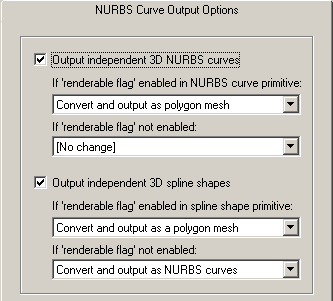
Output independent 3D NURBS curves
The NuGraf/PolyTrans 3D database has a very extensive NURBS curve sub-system. Each NURBS curve object can have 1 or more NURBS curves associated with it. Multiple curves inside a single object can either be considered to form a single continuous "composite" curve, or each curve can be considered unique, closed, planar (in world space) and oriented such that the curves of the object can be directly converted into a trimmed NURBS surface (in other words, the first curve forms the boundary of the surface and subsequent closed curves form the holes).The following options control how the various NURBS curve configurations can be converted during the export phase. An extensive internal NURBS curve conversion and cross-conversion system exists.
If 'renderable flag' enabled in NURBS curve primitive:
If the 'renderable' flag of a NURBS curve primitive is internally enabled, and the curve(s) form closed loops, then it is possible to convert the NURBS Curve primitive into a 3D format that is renderable: either a mesh, a trimmed NURBS surface or a Spline Shape. The following options define what will be done to NURBS Curves primitives during the export phase when their 'renderable' flag is enabled:[No Change]
No change. The NURBS Curve primitive will be exported as-is.Convert and Output as Polygon Mesh
The NURBS Curve primitive will be converted into a mesh object prior to export.Convert and Output as Trimmed NURBS Surface
The NURBS Curve primitive will be converted into a corresponding trimmed NURBS surface (patch). If the conversion process cannot be made then it will be output as a polygon mesh instead.If 'renderable flag' not enabled:
If the 'renderable' flag of a NURBS Curve primitive is not enabled then the curves will be considered just as plain curves that cannot be seen when rendered. In this case, the following options define what will be done to NURBS Curves primitives during the export phase when their 'renderable' flag is disabled:[No Change]
No change. The NURBS Curve primitive will be exported as-is.Output Composite NURBS Curve as a Single Curve
No change except in the case when the NURBS curve primitive is defined as a single composite curve made up of multiple curve segments. In this case the multiple curve segments will be temporarily converted to a single NURBS curve before export.Output independent 3D spline shapes
The NuGraf/PolyTrans 3D database has a very extensive spline primitive sub-system. This primitive accommodates one or more spline curves per primitive. If the multiple spline curves are each closed then the overall Spline Shape is termed "renderable" and can be thus converted into a polygon mesh or a corresponding trimmed NURBS surface (patch). For example, the letter "B" can be defined by 3 Bezier curves, the first forming the outer boundary and the latter two forming holes. Note, that unlike the NURBS Curve primitive, each spline curve of the Spline Shape is composed of only a single curve segment (no composite spline curves are allowed).The following options control how the various Spline Shape configurations can be converted during the export phase. An extensive internal Spline Shape conversion and cross-conversion system exists. The Spline Shape primitive also handles almost every major spline type (Bezier Spline, B-Spline, Cardinal Spline, Linear Spline, Tensioned Spline, TCB Spline), and their internal cross conversion (between spline types) or between the various spline types and a NURBS curve.
If 'renderable flag' enabled in spline shape primitive:
If 'renderable flag' not enabled:Convert and Output as Polygon Mesh
The Spline Shape primitive will be converted into a mesh object prior to export.Convert and Output as Trimmed NURBS Surface
The Spline Shape primitive will be converted into a corresponding trimmed NURBS surface (patch). If the conversion process cannot be made then it will be output as a polygon mesh instead.Convert and Output as a NURBS Curve Object
Each spline curve of the Spline Shape primitive is resampled into a corresponding NURBS Curve segment and placed into a single NURBS Curve primitive. The 'renderable' flag of the new NURBS Curve primitive will be disabled. The final NURBS Curve primitive will look similar (within an error tolerance) to the original Spline Shape.
This dialog box controls how referenced bitmap files will be handled during the export process. The three options are basically:
- Do not modify the bitmap filename reference and do not perform any bitmap conversion. This is useful if your bitmaps are already in a format recognized by the destination 3D program.
- Perform bitmap conversion for those file formats not recognized by Softimage and change the file extension of the bitmap. For example, if exporting to a file which references a bitmap called "brick.iff" (in the Amiga IFF file format), then this dialog box can enable the export converter to convert the Amiga IFF bitmap file to a recognized file format such as Softimage PIC.
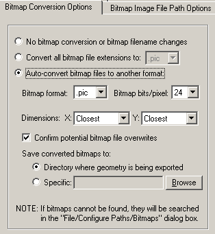
No Bitmap Conversion or Bitmap Filename Changes (Radio Button)
If this radio button is chosen then any exported bitmap references will not be changed, its filename extension wont be changed, the path to the bitmap will not be changed and no bitmap conversion will be done.Convert all Bitmap File References To... (Radio Button)
Rather than convert referenced bitmap images to another file format this radio button (when selected) simply changes all the file extensions on bitmap files to a specific type. For example, if set to "PIC" then all exported bitmap filenames will be changed so that their file extensions end in ".pic". This is a useful option is you already have all of the referenced texture maps converted to the desired file format.Auto-Convert Bitmap Files to Another Format (Radio Button)
If this radio button is selected then all 2d bitmap textures which are currently defined and referenced by the internal NuGraf/PolyTrans database scene will be automatically tagged then converted to a new user-specified 2d bitmap file format. For example, if the scene makes references to IFF bitmap files then this option can be enabled so that the IFF images get converted to PIC format automatically.If the bitmap texture(s) cannot be found in the location specified by the pathname prepended to the texture filename then the export converter will search for the texture(s) in all directories specified in the file search paths (these can be modified by choosing the File/Configure Paths dialog box and clicking the Bitmaps tab).
Bitmap File Format (Combo Box)
This combo box lists the destination bitmap file format.Bitmap Bits/Pixel: 2, 4, 8, 24 (Combo Box)
This combo lists determine the number of bits/pixel to write out to the new 2d bitmap file. The default is 24 bits. A color quantization algorithm will be used for the 2, 4 and 8 bits/pixel output formats. Not all bitmap file formats can accept 2-8 bits/pixel (in particular JPEG).Dimensions: X = #, Y = #
These two drop-down list boxes determine the X and Y resolution for the converted bitmap file(s):
No Change = Do not change the X or Y size Closest = Use the next highest power-of-2 size 2, 4, 8, ... 256, 512 = Choose a specific size for the X or Y dimension Confirm Potential Bitmap File Overwrites
If this checkbox is enabled (checkmarked) then the bitmap converter will confirm any potential overwrites of existing bitmap files on disk which have the same filename and extension as the one being written. If this option is disabled then no confirmation will be made.Save Converted Bitmaps To...
These radio buttons determine where the new bitmap file will be written to. Note that enabling the Replace all Bitmap File Paths With This Path: option or the Strip File Paths From All Bitmap References option below will change the path prefix for the converted bitmap even though it was saved to disk in the location specified by one of these 3 radio buttons.Directory Where Geometry Is Being Exported
The new bitmaps will be written to the directory where the exported files are being written to.Specific + Browse
The new bitmaps will be written to the directory specified by the text box. This directory can be changed by press the Browse button.
This panel controls how bitmap file paths will be processed before being placed in the exported file. File paths are used to proceed bitmap image filenames and basically allow specific directory or URL paths to be assigned to a bitmap image.
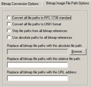
Convert all file paths to RFC1738 Standard
If this option is enabled (checkmarked) then all bitmap file paths written to the file will be converted into the "RFC 1738" URL format specification. This option is only used in the VRML2 exporter and is provided in this Softimage dotXSI exporter for convenience.This option will override the "Convert all file paths to UNIX format" when enabled. However, the conversion to RFC1738 will not be done when a valid string is specified for the "Replace all Bitmap File Paths With This URL Address" option below (since it is assumed the URL address string specified is already in RFC1738 format). As examples:
C:\polytrans\bitmaps\texture.tif --> file:///C|/polytrans/bitmaps/texture.tif
\\machine\polytrans\bitmaps\texture.tif --> file:////machine/polytrans/bitmaps/texture.tif
Convert all file paths to UNIX format
If this option is enabled (checkmarked) then all bitmap file paths written to the file will be converted to a UNIX compatible format (it will not take effect if the "Convert all file paths to RFC1738 Standard" option is enabled). In particular, all DOS- specific backward slashes \ will be converted to UNIX forward slash / directory separators. Also, any DOS-like drive specifiers, such as "c:\" will be removed from the file path and a warning message will be reported about the removal of this drive specifier (you should make sure that all DOS-like drive specifiers be replaced by UNC specifiers, such as \\machine1\). If this option is disabled then no conversions will be made.Strip File Paths from All Bitmap References
If this option is enabled (checkmarked) then any file paths on a bitmap reference will be stripped off. For example, "C:\polytrans\bitmaps\texture.gif" will be output as "texture.gif".Replace all Bitmap File Paths With This Absolute File Path:
This option allows all exported bitmap references to be prefixed with a new filepath. This might be useful, for example, if all of your bitmap files are located in one specific directory or if you wish to change the prefix on the imported bitmap references. This new path will override all other options on this bitmap conversion dialog box (in other words, it will replace a bitmaps file path regardless of any other file path added to the bitmap via other options in this dialog box). To choose the filepath press the "Browse" button. To disable this option type any character into the "Replace all Bitmap File Paths With This URL Address" type-in line, then delete that character.Replace all Bitmap File Paths With This Relative File Path:
This is the same as the previous "Replace all Bitmap File Paths With This Absolute File Path" option except that you can specify any arbitrary file path by typing the text into the type-in field. Whereas the previous method only allowed absolute file paths (ie: "C:\polytrans\bitmaps\texture.gif"), this option allows for relative file paths (ie: "bitmaps\texture.gif"). To disable this option, delete all text in the type-in field.Replace all Bitmap File Paths With This URL Address:
If this option is enabled (checkmarked) then all bitmap filenames (used in association with a texture map) will be prefixed with the string specified in the URL type-in. For example, if a texture references the filename:c:\files\textures\bitmap.tifwithin this programs database, and the URL is specified on this dialog box as:
http://www.okino.com/images/then the bitmap filename will be stored in the file as:
http://www.okino.com/images/bitmap.tif


