

| You are here: Home » Import CAD Formats » AutoCAD-Revit-Navisworks (DWF-3D) |
Support: 905-672-9328 Copyright © 2026 Okino Toronto, Ontario, Canada. |
|
The USGS DEM geometry import converter imports, manipulates and converts digital elevation model (DEM) data as well as GTOPO30 DEM data. With the help of the public domain SDTS2DEM.EXE program, this importer can also read in the SDTS DEM file format (see below for more information about SDTS files). It can also read in the National Elevation Database (NED) by indirect means (see below).
The USGS DEM data is provided as a service of the United States Geological Survey (USGS). Each data set describes the elevation of semi-square regions of land for various locations across the U.S.A., Alaska, Hawaii and some surrounding areas of Mexico and Canada. The most accurate DEM data sets are sampled every 30 metres (7.5 minute DEMs) while the least accurate are sampled every 3 arc seconds (for 1:250,000 scale DEMs). See below for a description of the various DEM dataset types.
Since these datasets are abundant and available freely via the Internet, this converter can be put to good use for creating realistic (and accurate) 3d landscape geometry.
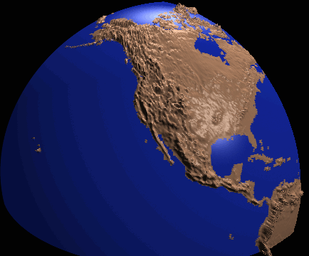
The dataset of the GTOPO30 can also be mapped into spherical co-ordinates by this import converter to create a spherical model of the globe as illustrated by this example (rendered with the Okino's NuGraf software):
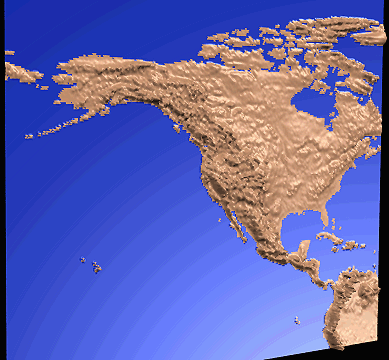
or the GTOPO30 data could be used to create a planar elevation of the earths surface as shown In this similar rendering:
DEM datasets typically contain 60000 or more quadrilateral polygons, or 1200000 triangles (for a 258x258 resolution sample; the maximum DEM dataset size if 2050x2050 which would result in 4.2 million quadrilaterals or 8.4 million triangles). This is an enormous number of polygons for most 3d rendering programs so this DEM converter incorporates two unique options to overcome this problem:
- The converter can skip over samples in the dataset so that only every n-th
sample is used. Rather than importing 258x258 samples, the converter imports
51x51 samples (for a skip factor of 5) which results in only 2601 quadrilateral
polygons.
- Rather than store the entire DEM dataset in single object, the DEM converter
breaks up the data into multiple smaller objects with a common parent. This
has shown to be an effective method to speeding up the wireframe redraws of the
DEM data (by a factor of 2 or 3), and makes interactive user movement of a 3d
camera much faster since each sub-object is only a few hundred polygons.
In addition, certain rendering programs
(such as Okino's NuGraf renderer) use much less memory when many smaller
objects are used rather than one large object with many polygons. By
default each sub-object stores a maximum of 900 polygons; contrast this with
other converters which lump all 120,000 polygons into a single object - few
renderers will be able to render such a large object.
- A default 3d camera is added to the scene which views the DEM data from a
pleasing angle.
- u/v texture coordinates are added to the imported data so that a bitmap image
can be easily draped over the DEM data.
- The converter creates smoothed vertex normals for the DEM data so that it will appear to be smooth when rendered.
In 1997 the United States Geological Survey (USGS) created a new, all-encompassing file format called SDTS which can hold many variations of the USGS data set archives. A SDTS dataset normally consists of 18 .ddf files which make up the spatial data transfer, rather than a single .dem file.SDTS 7.5min files can be found at these WEB locations:
http://mcmcweb.er.usgs.gov/sdts/data.html
http://mcmcweb.er.usgs.gov/sdts
The SDTS file format is very different than those supported in this DEM importer. To import SDTS files into this DEM importer you will have to use a common public domain converter called SDTS2DEM.EXE to convert the 18 .DDF SDTS files into a single USGS DEM file. To use the SDTS .DDF files with the SDTS2DEM.EXE program, the original SDTS files must have a naming convention similar to this:
xxxxCEL0.DDFIf the CEL0 is missing then the conversion will not work. If you have a file with a name something like:
xxxxLE##.DDFthen this is in a SDTS Digital Line Graph (DLG) directory and will not work with STDS2DEM. Refer to ftp://ftp.blm.gov/pub/gis/ for utilities to convert DLG files.
In 2004 the USGS office created the NED file format as described here: http://ned.usgs.gov.Quoting from their WEB site, "The USGS National Elevation Dataset (NED) has been developed by merging the highest-resolution, best quality elevation data available across the United States into a seamless raster format. NED is the result of the maturation of the USGS effort to provide 1:24,000-scale Digital Elevation Model (DEM) data for the conterminous US and 1:63,360-scale DEM data for Alaska. The dataset provides seamless coverage of the United States, HI, AK, and the island territories. NED has a consistent projection (Geographic), resolution (1 arc second), and elevation units (meters). The horizontal datum is NAD83, except for AK, which is NAD27. The vertical datum is NAVD88, except for AK, which is NAVD29. NED is a living dataset that is updated bimonthly to incorporate the "best available" DEM data. As more 1/3 arc second (10m) data covers the US, then this will also be a seamless dataset."
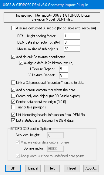
Assume Corrupted A Record (for possible error recovery)
If you import a DEM file and receive an error, such as Invalid profile number then enable this checkbox and try again. It may solve the previous error state.Explanation: USGS DEM files consist of 3 types of data records: A, B and C. The A record is the header information and is defined to be 1024 bytes in length. The latter part of this 1024 bytes is supposed to be blank spaces. However, we have experienced at least one USGS DEM file which has an A record less than 1024 bytes, ending in a CR/LF pair. If you enable this dialog box option then the importer will attempt to detect this short A record and skip to the next best possible starting point for the subsequent B record.
DEM Height scaling factor
This option scales the height of the DEM data. It default to 1.0. Values greater than 1.0 will make the DEM data higher while values between 0.0 and 1.0 will make the DEM data shorter.DEM Data skip factor (mesh quality)
This option determines the quality of the imported DEM data (it directly controls how many polygons will be used to approximate the input DEM data). THIS IS AN IMPORTANT CONTROL PARAMETER!! A value of 1 results in the highest quality mesh while higher values (2, 3, 4, etc) result in lower quality, but at the benefit of reducing the number of polygons in the input data. This number will cause the converter to 'skip' over every n-th input sample. For example, if the input dataset size is 258x258 samples, and the skip factor is set to 4, then the converter will actually read in the data as if it were of size 65x65 (258/4 = 65). This will produce 4225 polygons (65x65) instead of 66565 polygons. A value of 2 or 3 (16641 polygons to 7396 polygons) will produce good results for a final rendering, while values of 5 to 8 will produce small datasets ideal for fast previews (2704 polygons to 1024 polygons).Maximum size of sub-objects
By default the DEM data will be cut up into several smaller sub-objects rather than having all of the DEM data clumped together into one huge object. This option controls how many polygons will be put into each sub-object. The default is 30 which will cause 900 polygons (30x30) to be stored in each sub-object. The value range for this parameter is 5 to 100.List interesting header information from the DEM file
If the checkbox is enabled (check-marked) then the converter will print out information about the imported DEM data including the following information:
- The DEM data description from the file,
- The number of profiles which is the number of lines of sample data in the X direction,
- The projection mapping type (geographic, UTM or state plane),
- The actual geographic coordinates of the DEM dataset's four corners,
- The minimum and maximum elevations.
List statistics after loading the DEM data
If the checkbox is enabled (check-marked) then the converter will print out the number of objects and polygons created.Add default 2d texture coordinates
If the checkbox is enabled (check-marked) then u/v texture coordinates will be added to the imported dataset. These texture coordinates will allow a 2d bitmap image to be easily mapped to the surface of the data. Please note that the texture coordinates are aligned with the mathematical bounding quadrilateral of the dataset, not the actual physical edges of the data (this is because the physical edges of the data are not square or precise).Assign a default 2d bitmap texture
This option is only valid if the converter is running within the NuGraf Rendering System software. If this checbox is enabled (check-marked) then a default 2d bitmap texture file ('default.tif') will be linked to the DEM data. This option is useful if you intend to apply a 2d bitmap image to the DEM data. The 'Add default 2d texture coordinates' option must also be enabled.Once the DEM data has been imported, you can change the default bitmap image assigned to the data by pressing the 'Textures' tab on the Selector Window (within the NuGraf Rendering System software) then clicking and holding the left mouse down over the 'default dem texture' entry. A small pop-up menu will appear - choose the 'Edit Texture' menu item. The '2D Image Texture Parameters' dialog box will appear; press the Select button to choose the new texture bitmap. When done, press the 'Update and Exit' button on the dialog box.
U/V Texture Repeat
These two values determine how many times the 2d bitmap texture is to repeat across the DEM data surface (see the 'Assign a default 2d bitmap texture' option above). The default values are 5 which will make the texture repeat 5 times in the horizontal and vertical directions.Once the DEM data has been imported you can change the u/v repeat values by pressing the 'Surfaces' tab on the Selector Window (within the NuGraf Rendering System software) then clicking and holding the left mouse down over the 'default dem surface' entry. A small pop-up menu will appear - choose the 'Edit Surface' menu item. The 'Surface Attribute Editor' dialog box will appear; press the Texture Layers button so that the Texture Layer Editor dialog box appears. Now modify the values shown beside 'U/V Repeat'.
Link a 3d procedural 'mountain' texture to data
This option is only valid if the converter is running within the NuGraf Rendering System software. If the checkbox is enabled (check-marked) then a NuGraf "mountain" 3d procedural texture definition will be added to the scene and assigned to the current shader (useful for rendering the DEM data with the NuGraf renderer). This texture varies the color of the DEM data according to the elevation and slope of a polygon (the color varies from greens, to browns to whites at the highest altitudes). Please note that this texture tends to be slow to compute due to the turbulence math functions; a better alternative would be to assign a 2d bitmap texture.Add a default camera that views the data
If the checkbox is enabled (check-marked) then the converter will add a default camera to the scene which views the DEM data at a pleasing angle.Create only one object (for 3D Studio)
If the checkbox is enabled (check-marked) then one single object is created for all of the imported data rather than having the data broken up into multiple smaller sub-objects (the default). THIS OPTION SHOULD BE USED FOR DATA DESTINED FOR 3D STUDIO because 3D Studio requires all polygons to be inside a single object so that its smoothing algorithm will work properly; if multiple objects are used then the vertex normals will not be the same where the sub-objects meet and hence "cracks" may appear at the junctions.Center data about the origin (0,0,0)
If the checkbox is enabled (check-marked) then the DEM data will be centered about the origin (0,0,0). Please note that if the input DEM dataset uses the "Geographic" or "State Plane" grid types then the DEM data will always be centered about the origin; this may cause a problem if you want to import two DEM datasets and have them sit side-by-side; in this case you will have to physically move the two datasets so that they are side-by-side.Triangulate Polygons
If the checkbox is enabled (check-marked) then the DEM data will be imported as triangles instead of 4 sided polygons. This is sometimes useful to enable since 4-sided DEM data polygons are not planar.
GTOPO-30 is a new twist on the DEM data format. Data in this format can be obtained from http://edcwww.cr.usgs.gov/landdaac/gtopo30/gtopo30.html.Sea level height
By default sea level is at 0. This option specifies where the sea level is. It is most useful when the Apply water surface option is selected. By raising the sea level, more polygons are coloured in blue. All polygons of height less than or equal to the sea level are coloured in blue. This option is also affected by the DEM Height scaling factor option. For example if the sea level is 100 and the scaling factor 10, then sea level will appear to be at 1000. However, it will still maintain the correct propotional distance to the peaks of mountains.Map elevation data onto a sphere
Instead of loading the DEM data onto a flat plane, this option loads the data into a spherical format. This way it looks like the earth when rendered.Sphere radius
This option specifies the radius of the sphere that the data is mapped on. By default the radius is 60000.Apply water surface to undefined data points
When this option is checked, all data with elevation less than or equal to the Sea level height option (see above) is coloured in blue.
DEM elevation data spacing varies from 30 meters for 7.5-minute DEMs to 3 arc seconds for 1:250,000 scale maps. All DEM data are similar in logical data structure and are ordered from south to north in profiles that are ordered from west to east.
- 7.5-minute DEM data are produced in 7.5-minute units which correspond to USGS 7.5-minute topographic quadrangle map series. 7.5-minute DEM data consist of a regular array of elevations referenced horizontally on the Universal Transverse Mercator (UTM) coordinate system of the North American Datum of 1927 (NAD 27). These data are stored as profiles with 30-meter spacing along and between each profile.
- 15-minute DEM data correspond to USGS 15-minute topographic quadrangle map series in Alaska. The unit sizes in Alaska vary depending on the latitudinal location of the unit. 15-minute DEM data consist of a regular array of elevation referenced horizontally to the geographic (latitude/longitude) coordinate system of North American Datum 1927 (NAD 27). The spacing between elevations along profiles is 2 arc seconds of latitude by 3 arc seconds of longitude.
- 30-minute DEM data cover 30-minute by 30-minute areas which correspond to the east half or west half of the USGS 30- by 60-minute topographic quadrangle map series for the conterminous United States and Hawaii. Each 30-minute unit is produced and distributed as four 15- by 15-minute cells. 30-minute DEM data have the same characteristics as the 15-minute DEM data except that the spacing of elevations along and between each profile is 2 arc seconds.
- 1-degree DEM data are produced by the Defense Mapping Agency in 1-degree by 1-degree units which correspond to the east half or west half of USGS 1- by 2- degree topographic quadrangle maps series, for all the United States and its territories. 1-degree DEM data consist of a regular array of elevations referenced horizontally using the geographic (latitude/longitude) coordinate system of the World Geodetic System 1972 Datum. A few units are also available using the World Geodetic System 1984 Datum. Spacing of the elevations along and between each profile is 3 arc seconds with 1,201 elevations per profile. The only exception is DEM data in Alaska, where the spacing and number of elevations per profile varies depending on the latitudinal location of the DEM.