

| You are here: Home » Import CAD Formats » AutoCAD-Revit-Navisworks (DWF-3D) |
Support: 905-672-9328 Copyright © 2026 Okino Toronto, Ontario, Canada. |

This geometry import converter reads in FBX files of varying older and newer vintages. It provides import support for all major features in FBX files including support for polygon meshes, trimmed NURBS surfaces, NURBS curves, bicubic or linear patches, geometry hierarchy, lights, cameras, animation and mesh skinning.
If you are importing data from 3ds Max or Maya then please use Okino's PolyTrans-for-3dsMax or PolyTrans-for-Maya software. When importing from AutoCAD, Navisworks, Revit or Inventor please use Okino's native DWF-3D importer or native Inventor importer.
Please refer to the corresponding FBX exporter.
NOTE: Due to instabilities in the various Kaydara, Alias|Wavefront and Autodesk FBX SDK implementations, Okino has uniquely taken the initiative to develop multiple FBX import converters, each based on a different version and vintage of the FBX file format. Our software will auto-detect the version of the FBX file trying to be loaded and will choose an appropriate Okino FBX importer for the task.
Quick History of the Okino FBX Converter Implementations:
Long before many 3D users had even heard of the FBX file format, Okino Computer Graphics developed the first, professional FBX conversion system starting in November 2002 and continues to do so until this very day.
As such, Okino is the longest standing and experienced conversion company when it comes to all aspect of the FBX file format, its disparate and non-compatible SDKs and all of its many quirks. We produce the first and only long-standing implementations of FBX import/export converters that support v5 (Kaydara), v6 (Alias|Wavefront) and v7 (Autodesk).
An Import Conversion Example
The following is an example whereby an animated and skinned set of Samurai warriors were imported from a FBX file and rendered + animated in Okino's NuGraf software.
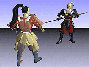
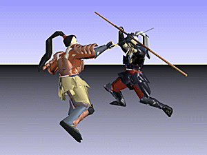
FBX 'Samurai' model (courtesy of Kaydara/Alias/Autodesk) imported, animated & rendered in Okino's NuGraf.
Click on any image to view a Windows Media 640x480 animation (2.3MB download).
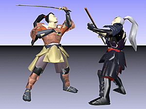
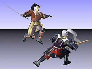
Click on any one of the small screen snapshots to jump to the corresponding section of this WEB page:
| Main | Selective-1 | Selective-2 | NURBS |
|---|---|---|---|
![[1]](imp_fbx_main_sml.gif) |
![[2]](imp_fbx_selective1_sml.gif) |
![[3]](imp_fbx_selective2_sml.gif) |
![[4]](imp_fbx_nurbs_sml.gif) |
| Units Matching | Materials | Animation |
|---|---|---|
![[5]](imp_fbx_units_sml.gif) |
![[6]](imp_fbx_materials_sml.gif) |
![[7]](imp_fbx_anim_sml.gif) |
- Okino was the first professional conversion company to fully implement the FBX file format from its get-go,
long before most people even heard of the file format. Okino is the only company to support the
full legacy family of FBX variations, including the v5 (Kaydara), v6 (Alias) and v7 (Autodesk) versions
of FBX (even though v5 is purely a long-dead 32-bit-only format). This
is handled in a most unique manner, by shipping 3 completely different FBX importers, one for each
variation of the file format.
- We know the FBX file format and all of its quirks better than any company. Having developed it
since the birth of the FBX format, we have seen it morph, twist and bend from version to version, and
hence handle all such oddities during import. You can most often import a 'bad' or old FBX file into
Okino software and re-export it again to FBX to make for a clean and legally compliant file.
- Reading of all FBX supported geometry including polygons, trimmed NURBS surfaces, NURBS curves and
patches. Geometric and vertex normals will be computed for geometry without such information.
- Import of materials, textures, texture mapping, lights and cameras.
- Full object hierarchy import into Okino software with user selected hierarchy optimization algorithms.
- Import of character skinning information.
- Import of camera animation, lights animation, object animation and fully skinned character animation. Import of all animation FCurve interpolation types (constant, linear or cubic) as well as all tangent modes (auto, TCB, user, break).
The following sections provide a cursory overview about how many of the elements of a FBX file are imported and converted to the internal Okino scene graph database:
Geometry Import Translations
In FBX format, geometry can be represented as polygon meshes, trimmed NURBS surfaces or bicubic patches. Patches can be Bezier, Bezier Quadratic, Cardinal, BSpline or Linear. The FBX importer will convert all patches to NURBS surfaces during import. If you deselect the NURBS import checkbox, you will also be implicitly deselecting the import of any patches. If you select to import NURBS and to convert them to polygon meshes by enabling the "Convert NURBS to Meshes" checkbox, then any imported patches will also be converted to polygon meshes.NURBS Import Translations
Okino software imports all types of trimmed NURBS surfaces (open, closed or periodic) currently implemented in the FBX format. All closed and periodic NURBS patches will be converted to open NURBS during import.NURBS Limitations:
Textures on NURBS may not have accurate UV co-ordinates. Even if NURBS are converted to Polygons on import the UV co-ordinates on the resulting polygons may still not be accurate (in this case, the UV co-ordinates will be determined by using a spherical projection onto the geometry in question).
FBX Geometry Okino Geometry N - sided Polygons N - sided Polygons Open NURBS Open NURBS Closed NURBS Open NURBS Periodic NURBS Open NURBS Patches NURBS Materials Import Translations
The FBX importer supports ambient, diffuse, specular and emissive colors as well as opacity, shininess and reflectivity. Phong, Blinn and Lambert FBX shading models are all supported.
FBX Shading Model Okino Shading Model Blinn Blinn Lambert Blinn Phong Phong * any other shading model Blinn
FBX Material Parameter Okino Material Parameter Opacity Opacity Shininess Shininess (100x bigger than FBX Value) Reflectivity Reflectivity Ambient Ambient Diffuse Diffuse Specular Specular Emissive Luminous Texture Import Translations
Imports per-polygon texture mapping, texture scaling and texture modulation.Lights Import Translations
Point, directional and spot lights are imported. Since FBX spotlights have a position and an orientation, whereas Okino spotlights have a position and a shine-at location, any spotlights will be converted have equivalent position and shine-at settings.These FBX items will not be imported:
- Global Light Settings
- All Fog related setting are not imported:
- Fog Color
- Fog Density
- Fog Start and End
- All Shadow related settings are not imported:
- Shadow Intensity
- Shadow Planes
The only parameter imported from the Global ambient light in FBX is the color of that light.
Since lights are imported into their own hierarchy list in Okino software they may need to reparented in the destination application to their original position in the object hierarchy in order to maintain their correct settings.
FBX Gobos are not imported.
Cameras Import Translations
There are 2 types of camera's in FBX - Global cameras and User Defined cameras.
Note: if a user defined camera is the default camera in an FBX scene, then all camera specific parameters and animation is lost on this camera during import.
Since cameras are imported into their own hierarchy list in Okino software they may need to reparented in the destination application to their original position in the object hierarchy in order to maintain their correct settings.
A camera has a Look-At Node in the FBX format. If this Look-At Node for a particular camera is set to any node that doesnt have the FBX root node as its direct parent, then animation data for this Camera may not be converted properly.
Skinning Import Translations
The FBX format supports what are referred to as the "Normal, Total1 and Additive" skinning modes. This importer and the Okino scene graph supports the Normal and Total1 modes completely but not the Additive mode. The Additive mode is equivalent to what is referred to as "point clusters" in other applications such as Maya.Limitations & Problems of Importing "Bind Poses" from FBX File Format
In order to import skinning correctly it is essential to import the unique global bone and mesh Bind Pose. Due to known issues with the FBX SDK, it is sometimes not possible to get these critical Global Bind Poses, as sometimes only the relative "bone to mesh" transformations are known during import. The FBX importer applies a certain algorithm to attempt to determine these global bind poses.
If it is known that the correct Bind Poses were imported, then no warning messages with respect to this are output to the importer's message window. If however, the importer is unsure of whether or not the correct Bind Poses were detected, then a warning message is sent to the console.
FBX Skinning Mode Okino Skinning Mode NORMALIZE Mesh Skinning TOTAL1 Mesh Skinning - extra bone added at mesh centre ADDITIVE Not Supported Animation Import Translations
FBX format includes support for multiple animation "Takes" within a single file. When there is more than a single animation take available within an FBX file, the drop down listbox labelled "Take" in the FBX import dialog box will be populated with all available takes in the FBX file in question. Select the desired take to import.
During animation import, you can choose to maintain animation data in it's native representation where possible or to resample the animation keyframe data.
Animation Import Limitations:
Quaternion animation is usually the preferred method for animations of rotational quantities, but these are not currently supported in the FBX format.
F-Curve translations
Although Okino software does support many different kinds of F-Curve representations, there are minor differences in the internal representations of animation F-Curves. The table below illustrates these differences.
FBX FCurve Interpolation Okino FCurve Interpolation All Constant Constant All Linear Linear All Cubic with TCB tangeant mode. TCB All Cubic with mixed auto, user, break or TCB tangeant modes. Bezier Mixed Interpolation types. FCurve is resampled at 15fps and the interpolation type set to Linear.
FBX FCurve Extrapolation Okino FCurve Extrapolation Constant Constant Slope Gradient* Repetition Cycle* Mirror Repetition Cycle (not true mirror repetition) * - Different terminology used between FBX and Okino, but these modes are exactly equivalent i.e. 'Slope' is equivalent to 'Gradient' and 'Repetition' is equivalent to 'Cycle'.
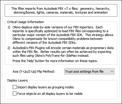
Axis (Y-Up / Z-Up) Flip Method
Over the decades there has become two standards for the Up axis in most 3D software, either the Y axis or the Z axis. AutoCAD/Microstation/Rhino-like derived modelling software, that goes back to the 1980s, will most often use the Z axis as Up whereas other programs, such as DCC/Animation programs written in Canada (Maya, Softimage, Houdini, Cubicomp, Neovisuals, etc.) will use the Y axis as Up. Since FBX was never written as a 3D file format standard there is really no well defined Up Axis for all the various FBX files which have been written since the early 2000s. This combo box allows the imported FBX file to be re-oriented into the proper Up direction. Okino software uses a standard "Y" up coordinate system.Trust Axis Settings from File
FBX has an indicator which defines the preferred Up axis of the file. However, that indicator is not always valid. Choosing this option will derive the Up axis from that which is defined by the FBX file.Assume File Data is Z-Up
Choosing this option will force the Z axis to be the Up Axis regardless of whatever is defined inside the FBX file.Assume File Data is Y-Up
Choosing this option will force the Y axis to be the Up Axis regardless of whatever is defined inside the FBX file.Display Layers
Shapes and geometry within FBX can be assigned to different layers, each with their own special attributes such as hidden state.Output Display Layers as Grouping Nodes
Okino software does not use the CAD concept of layers but rather uses the more common and widespread use of hierarchies of object definitions. If this checkbox is checkmarked then each FBX layer will be converted into an Okino grouping folder (node) whose children will be those objects assigned to the corresponding FBX layer.Force Objects on all Display Layers to be Visible
If this checkbox is checkmarked then all display layers which are marked as being hidden will instead be imported as fully visible.
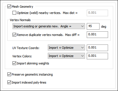
Mesh Geometry
If this checkbox is checkmarked then mesh geometry will be imported from the FBX file. Normally you would always want to keep this option enabled.Optimize (weld) nearby vertices. Max distance = #
This function will delete all redundant vertices from the polygonal mesh geometry which are within a specified distance of each other. The default distance is shown on the dialog box. This option is enabled by default so that the imported FBX mesh geometry is more refined and welded together. Most destination 3D programs will expect the mesh geometry to be in this refined, welded format.Vertex Normals
Vertex normals are used to specify where an object is to appear smooth and where it is to appear faceted (rough).Combo Box:
This combo box determines what is to happen to the vertex normals during the import process:Do Not Import
No vertex normals are imported. The resulting polygonal meshes will appear faceted in the destination 3D program.Import Existing Values
The vertex normals from the FBX file will be imported as-is.Generate New Values. Smoothing angle = #
Brand new vertex normals will be automatically generated based on a smoothing angle. The vertex normals from the FBX mesh data will be ignored. Normally you would not want to use this method unless you do not like the vertex normals on the FBX mesh data and wish to override them with automatically computed values.The vertex normals are computed based on the angle between abutting polygons. If the angle between the geometric surface normals of abutting polygons is less than the 'Smothing Angle' type-in value (in degrees) then newly computed vertex normals will be assigned to the polygons (they will be smoothed). Higher values make the object appear to be smoother and have less sharp corners (such as 40 to 60 degrees).
Import Existing or Generate New. Smoothing Angle = #
This is the default. If explicit vertex normals are found on the FBX mesh data then they are imported directly. If none exist then new vertex normals will be computed as per the method in the previous paragraph.Remove Duplicate Vertex Normals. Max diff = #
This is the same as the 'Optimize (weld) nearby vertices' function except that it combines redundant normals that are within a certain threshold of each other. It can make for more optimized imported meshes and possibly smaller files.UV Texture Coordinates:
UV texture coordinates are a vital aspect of 2D bitmap image texture mapping. They are 2D values associated with a FBX polygonal mesh object which defines how a planar bitmap image is to be draped over top of the mesh. This combo box determines what will be done to those texture coordinates during the FBX import process.Do Not Import
No vertex texture coordinates are imported. The resulting polygonal meshes will not be texture mapped as a result.Imported (Unoptimized)
The original FBX vertex texture coordinates will be imported as-is.Import + Optimize, Tolerance = #
The original FBX vertex texture coordinates will be imported as-is but also any redundant coordinates will be deleted based on the threshold value shown on the dialog box (any texture coordinates within a threshold of that value from each other will be welded into a single coordinate value, thus making the imported data more optimized and possibly smaller in size).Vertex Colors:
Vertex colors were somewhat more common in 3D file formats (like OpenFlight) back in the 1980s and 1990s before realtime 3D texture mapping became more prevalent. They allow explicit RGB colors to be associated with each mesh vertex. This combo box determines what will be done to those vertex colors during the FBX import process.Do Not Import
No vertex colors are imported.Imported (Unoptimized)
The original FBX vertex colors will be imported as-is.Import + Optimize, Tolerance = #
The original FBX vertex colors will be imported as-is but also any redundant colors will be deleted based on the threshold value shown on the dialog box (any vertex colors within a threshold of that value from each other will be welded into a single RGB color value, thus making the imported data more optimized and possibly smaller in size).Import Skinning Weights
If this checkbox is checkmarked then skinning weights will be imported along with each vertex coordinate. Skinning weights are a fundamental aspect of doing mesh deformations via skeletons and bones. Each skin weight value determines how much a specific bone will influence one mesh vertex.Preserve Geometric Instancing
If this checkbox is checkmarked then the mechanism of "instancing" will be used to try and keep the size of the imported FBX file as small as possible. For example, if the source file has 1000 bolts all derived from the same mesh primitive data, and the 1000 items have been placed in the FBX file via "instancing" then only a single copy of the geometry mesh data will be imported, but with 1000 virtual copies made of it. These virtual copy instances merely act as indexes to the original mesh primitive data instead of being full copies, which can significantly reduce the size of the final output.If this checkbox is disabled then unique and explicit copies of mesh data will be imported from the FBX file regardless of whether each copy is exactly the same as previous copies already imported.
Note: instancing is disabled on both the Okino FBX importer & exporter by default. So, if you are testing the round-tripping of a file with instancing then please make sure to enable the Okino FBX "instancing" checkbox on both the importer and exporter options dialog boxes.
Import Indexed Polylines
If this checkbox is checkmarked then 3D polyline geometry will be imported from the FBX file.
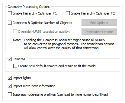
Geometry Processing Options
Hierarchy Optimizer # 1, Hierarchy Optimizer # 2
These options provide methods to remove redundant hierarchy nodes (NULLs, or grouping folders) from the imported file. Optimizer #1 removes runs of empty folders, as well as folders with no children. Optimizer #2 is simpler, deleting empty folders which only have 1 geometry object in them. These options can also be enabled via the Optimize hierarchy after completion checkbox found on the options dialog box of the Compress & optimize number of objects option (see below).Compress & optimize number of objects
This checkbox enables one of the most important and critical scene processing functions in all of Okino software. It is an integral and core part of any Okino CAD converter, and it has been added to the FBX importer for added benefits.The primary purpose of this function is to walk the imported geometry hierarchy and compress together all objects that are parented under a single folder into a one new object. For example, if you have a scene with 200 parts that are grouped under one assembly node then enabling this option will cause all such occurrences to collapse the children geometry of each imported assembly node into one object definition.
The documentation for this option can be viewed by pressing the "Options " button and then the "Help" button on the optimizer's dialog box.
Note: enabling this checkbox will cause all NURBS surfaces to be converted to polygonal meshes.
Override NURBS Tessellation Quality
When the 'Compress & Optimize Number of Objects' option is enabled then all NURBS surfaces must first be converted to polygonal meshes. The quality of the resulting meshes can be optionally controlled by enabling this checkbox and changing the NURBS tessellation override values accessible via this button:
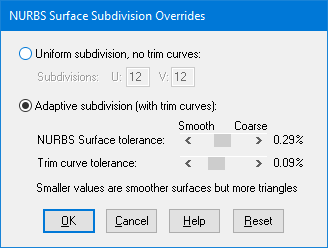
Uniform Subdivision, No Trim Curves
This subdivision method simply subdivides the NURBS surface into a uniform mesh of U by V number of rectangular polygons. It produces the fastest tessellation of a NURBS surface but it does not allow for NURBS surfaces to be trimmed by trimming curves.Adaptive Subdivision (with trim curves)
This method adaptively subdivides the NURBS surface based on its curvature. Areas with high curvature will be subdivided more finely. This method also allows the NURBS surfaces to be trimmed by trimming curves (if there are any associated with the NURBS patches) at the expense of making the tessellation process slower.The number of polygons used to approximate the true NURBS surface (or, its smoothness) is controlled by the Surface Tolerance slider. Lower values will make the surface smoother but at the expense of a longer tessellation time and more resultant polygons. This slider represents the maximum allowable distance (tolerance) between the true NURBS surface and the tessellated polygonal surface; it is measured as a percentage of an objects maximum bounding box size. For example, if a NURBS surface is being tessellated which is 10x10x10 units in size, and this slider is set to 0.2% then the resultant polygonalized surface will not deviate from the ideal NURBS surface by more than 0.02 units (2% of 10).
The Trim Curve Tolerance slider is used to control the smoothness of the NURBS trimming curves. Lower values will make trimmed curve regions smoother, but again at the expense of a longer tessellation time and more resultant polygons. This slider represents the maximum allowable distance (tolerance) between the true NURBS curve and the tessellated polygonal curve; it is measured as a percentage of an objects maximum bounding box size (the object on which the curve lies). For example, if a NURBS surface is being tessellated which is 10x10x10 units in size, and this slider is set to 0.2% then the resultant polygonalized NURBS curve will not deviate from the ideal NURBS curve by more than 0.02 units (2% of 10).
Import Cameras
If this checkbox is checkmarked then perspective and orthographic cameras will be read in from the FBX file.Create New Default Camera and Resize to Fit the Model
If this checkbox is enabled then a brand new Okino-specific 3D perspective camera will be created and made the "default" camera. The camera will be arbitrarily zoomed out to view the entire imported FBX model. This new camera will not have any relation to the cameras and views contained in the source FBX file. If this option is disabled then no new 3D perspective camera will be created.Import Lights
If this checkbox is checkmarked then ambient, directional, point (position) and spot lights will be read in from the FBX file. All other light types will be ignored.Import Meta-Data Information
Enabling this option will convert and import FBX Attributes that have been associated with each object (referred to as Meta data in Okino terminology). FBX Attributes are things like Material type, Name, Cost, etc. as well as custom user defined attributes The data will be imported either as integer numbers or strings to the Okino 3D scene database.
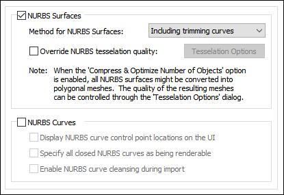
Import NURBS Surfaces
If this checkbox is check-marked then trimmed NURBS geometry will be imported from the FBX file. Please note that you should not, in general, use FBX to convey trimmed NURBS geometry nor CAD data, as it is based on the old-school, 1990s form of NURBS and not of the new-school method of BREP Manifold Solids geometry.Method for NURBS Surfaces
This combo box determines if the trimming curves are to be imported along with the base NURBS geometry.Override NURBS Tessellation Quality
Refer to the full explanation on the Selective Import Options Panel # 2.NURBS Curves
These options are used when NURBS curves are being imported from FBX. In general you should never have to touch or worry about changing these options.Display NURBS Curve Control Point Locations on UI
If this checkbox is check-marked then the control point (CV) locations used by any 3D independent NURBS will be displayed. This option is only applicable when viewing imported NURBS curves within the Okino stand-alone software.Specify all closed NURBS curves as being renderable
If a NURBS curve forms a closed loop, and this option is enabled, then those curves will be flagged as being "renderable". This only has significance to the Okino stand-alone software in which case such "renderable" curves can be scanline or ray traced rendered as a 3D surface and not just a 3D curve.Also, if the curve loop is set as renderable, then it can be (optionally) converted into a trimmed NURBS 3D surface.
Enable NURBS curve cleansing during import
If this option is enabled then the NURBS curves will be "cleansed" (multiple knots removed as best can be done, and the knot vector is clamped). This option is enabled by default.
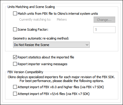
Units Matching and Scene Scaling
Match units from FBX file Okino's internal system units
These options determine what will be done when the units defined in the current FBX scene do not match those of the destination Okino internal system units (which is listed on the dialog box as the Current matching to units).
If the units do not match then the importer will rescale the imported geometry based on the ratio between the FBX units and the current Okino internal system units (the Current matching to units).
If this checkbox is enabled then the importer will rescale all imported geometry so that the units of the FBX file will be made to match the current Okino internal system units. If the checkbox is disabled then the geometry will be imported unchanged and untouched, meaning that its scale may be "incorrect".
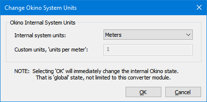
Internal System Units
This drop-down combo box specifies the current units system in effect within the internal Okino scene graph. It defaults to meters. What you need to do is select an appropriate entry from the drop-down combo box which matches the system units used by your destination program:
None No units; never do any geometry scaling Custom Custom units are in effect. See below Microinches 1e-6 inches Mils 1e-3 inches Inches 0.0254 meters Feet 12 inches Miles 63360 inches Microns 1e-6 meters Millimeters 1e-3 meters Centimeters 1e-2 meters Meters Kilometers 1e+3 meters Custom Units in "Units Per Meter"
If the drop-down "Internal System Units" combo box is set to "Custom", then this edit text control defines the "units per meter" scale factor for the custom unit system.Scene Scaling Factor = #
This option allows the imported scene to be scaled larger or smaller by a user specified amount.As examples, enter these values:
- 1.0, no scene scaling
- 1000, scale 1000 times larger
- 0.001, scale 1000 times smaller
- 4, scale 4 times larger
- 0.25, scale 4 times smaller
You can enter a value into the edit box specifying a relative scaling factor, and the model will be scaled by this factor. For example, if you enter '2.0', the model will come out twice as large.
Geometry automatic re-scaling method:
This combo box provides access to a useful mechanism which automatically rescales the imported geometry to a size best needed by other 3D software packages. This combo box can be used to automatically resize any imported model data to a useful size, such as scaled to easily fit inside a box of 2x2x2 raw working units. The various options are described as follows:Do Not Resize the Scene
No resizing is done to the imported data.Resize to 1x1x1 units
Resize to 2x2x2 units
The model data is automatically scaled up in size, or scaled down in size so that its world space extents fits inside a 1x1x1 or 2x2x2 sized unit cube.Resize to User Defined Absolute Size
The model data is automatically scaled up in size, or scaled down in size so that its world space extents fit inside a cube whose size is user defined by the type-in value shown on the dialog box. For example, if you enter the value 20 then the imported data will be resized so that its maximum extent in one or more dimensions is 20 units.Scale Larger by User Defined Factor
Scale Smaller by User Defined Factor
These options allow the imported model data to be scaled larger or scaled smaller by an absolute number. For example, if you select the larger option and enter 10 into the type-in box, then the imported model will be scaled 10 times larger during the import process.Report Statistics about the geometry file
If you enable this checkbox, statistics about the imported FBX file will be displayed in the console. Statistics will be displayed for the following:
- Version of the imported file
- Currently used FBX SDK Internal Version
Statistics will also be displayed for the number of:
- Polygons imported
- NURBS surfaces imported
- NURBS curves imported
- Cameras imported
- Lights imported
- Surfaces imported
- Textures imported
- Animation F-Curves imported
- Animation Keyframes imported
- Joints imported
Report Importer Warning Messages
This will print all warning messages to the importer's console. A warning does not necessarily mean that any degradation of data has occurred or that an error has occurred.Note that deselecting this option will only cause warnings to be suppressed, not statistics or errors. If there is an error that would cause the importer to abort, then this is printed to the console when the process is aborted regardless of whether or not the "Print Warning Messages" option has been checkmarked.
FBX Version Compatibility
Okino is the only company which develops completely different 3D import converters for each major release of the FBX file format. This is due to the (generally) wide spread discrepancies, oddities and incompatibilities introduced into the FBX file format from version 5 (Kaydara), version 6 (Alias|Wavefront), version 7 (Autodesk) and newer.By default this specific importer will explicitly not import older or newer releases of the FBX file format but rather only the version for which it was designed for. However, this behavior can be overridden by toggling on either of the following two checkboxes.
Attempt import of newer FBX v8 and higher files (via FBX v7 SDK)
If this checkbox is checkmarked then this importer will attempt to load FBX v8 or newer files using this importers FBX v7 SDK.If this checkbox is not checkmarked then this importer will not import any FBX v8 or newer files (leaving that job for another Okino FBX importer to handle).
Attempt import of older FBX v5 & v6 files (via FBX v7 SDK)
If this checkbox is checkmarked then this importer will attempt to load FBX v6 or older files using this importers FBX v7 SDK.If this checkbox is not checkmarked then this importer will not import any FBX v6 or older files (leaving that job for the existing Okino FBX v5 and v6 importers to handle).
!! NOTE !! if an imported scene has its texture maps looking too bright or washed out then try one of these two suggestions:
- Enable the "Merge and mix ambient color into diffuse color" checkmark option. Then manually disable or delete the default ambient light inside of the destination program.
- Or, enable the Set diffuse color of textured materials to white checkmark option. This will set up better shading parameters for the final imported scene file.
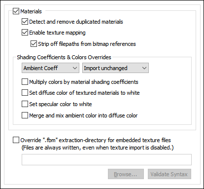
Enable Material Import
If this checkbox is checkmarked then materials will be imported from FBX.Detect and remove duplicated materials
If this checkbox is checkmarked then materials which are not associated with any geometry objects will not be imported from the FBX file.If this checkbox is uncheckmarked then every material of the scene will be imported from the FBX file, regardless of whether they are used or not by any geometry objects.
Enable texture mapping
If this checkbox is checkmarked then 2D texture image maps that have been assigned to geometry will be imported from the FBX file as an Okino texture definition.Strip off filepaths from bitmap references
Texture image maps are often associated with a directory file path and filename to define their location on disk such as c:\my texture maps\brick.jpeg. By Okinos rules of data translation, it is better to not include the file path along with the texture image name. If this checkbox is checkmarked then the c:\my texture maps prefix will be stripped off the bitmap reference.Shading Coefficients & Colors Overrides
These combo box options allow the various imported material attributes to be fine tuned or outright modified. The two combo boxes and the single numeric text box provide you good control over the ambient, diffuse, specular, opacity and shininess shading coefficients imported from the FBX file.The first drop-down combo box selects which of these shading parameters is to be modified. Each shading coefficient has its own operation that can be selected (via the second combo box) and an optional numeric text value (via the third data entry text input box). The following describes the various shading parameters that can be controlled:
- Ambient Coefficient: This controls the amount of color reflected from an object based on the ambient light in a scene. A good default value is 0.1 through to 0.3 and ideally ranges from 0.0 to 1.0.
- Diffuse Coefficient: This controls the amount of color reflected from an object based on the direct light shining on it. A good default value is 0.4 and ideally ranges from 0.0 to 1.0.
- Specular Coefficient: This controls the intensity of the highlight color on an object. A good default value is 0.7 and ideally ranges from 0.0 to 5.0.
- Opacity: This is the inverse of transparency. 0.0 will make the object fully transparent, while at 1.0 the object will be fully opaque.
- Phong Shininess: This controls the width of the specular highlight seen on an object. An ideal range is 6 (very wide) to 300 (very narrow). The default is 32.
For each material shading parameter, several actions can be performed on each material shading parameter during the import process:
- Do Not Import: The shading parameter is not imported at all. No value is imported nor sent to the Okino software. Thus, the default material shading parameter value (as set inside Okino software) will be used instead.
- Import Unchanged: The shading parameter is imported as is, with no change.
- Set and Use Default: The shading parameter is set to some "good" default value (as determined by the import converter). This default value will be shown in the type-in box.
- Set to Specific Value: The imported shading parameter will be overridden with the user specified value of the numeric type-in box.
- Import and Crop by: The shading parameter is imported and will remain unchanged if it is less than the numeric type-in value shown on the dialog box. If it is greater, then the imported value will be clamped to be no greater than the numeric type-in value. This is a good operation, for example, if you do not wish for the ambient shading coefficient to be greater than 0.3.
- Import and Scale by: The shading parameter is imported and multiplied by the numeric type-in value shown on the dialog box
Multiply colors by material shading coefficients
Inside Okino's internal scene graph each material has a "color" and a corresponding "shading coefficient" for each ambient, diffuse, specular and luminous color definition. The "shading coefficient" can be considered a variable intensity control that brightens or darkens its corresponding color, without having to modify the color itself.If this checkbox is checkmarked then each shading coefficient is multiplied into its corresponding color value after being imported from the FBX file.
If this checkbox is not checkmarked then only the raw colors will be imported from the FBX file (ambient, diffuse, specular and luminous) and their corresponding shading coefficient values will be ignored. This will typically result in brighter, bolder and punchier materials, what we ourselves term "OpenGL" shading which tends to be more saturated than colors seen in photo-realistic rendering programs.
Set diffuse color of textured materials to white
This is one of those options that may come in handy for someone with particular requirements for their textured objects being imported from the FBX file. If this checkbox is checkmarked then any material which has a diffuse texture map assigned to it will be imported in such a way that its underlying diffuse surface color will be set to white.This is useful because certain real-time renderers use an "OpenGL" shading model in which the diffuse color is multiplied into the assigned texture map colors - if the diffuse material color is dark or black then the texture map will not be visible (often a problem when exporting from Maya for which the diffuse surface color is always set to black for textured materials). Enabling this option will cause the diffuse surface color to become white, and thus it will not affect the brightness of the assigned texture map.
If this checkbox is not checkmarked then the diffuse surface color will be imported unchanged.
As noted at the start of this section of help file, this option can be enabled in case texture maps look too bright or washed out after being imported from the FBX file (as one of two possible suggested methods).
Set specular color to white
If this checkbox is enabled then the specular material color will always be set to white (although, the white can be dimmed by changing the 'Specular Coefficient' material parameter override, as described above). If disabled, then the real material's specular color will be imported.Merge and mix ambient color into diffuse color
Enabling this checkbox will cause the materials ambient color to be mixed into the diffuse material color before the final diffuse color is imported.Override '.fbm' Extraction-Directory for Embedded Texture Files
FBX files have the ability to contain embedded texture bitmap images. The FBX SDK will always extract these bitmap images to disk even if texture mapping is disabled on this Okino FBX importer. If the name of the imported FBX file is 'filename.fbx' then the texture bitmap images will be automatically extracted to a new sub-directory titled 'filename.fbm'.If this checkbox is enabled then you will be given the ability to override the directory into which these bitmap image files are saved into. That directory must presently exist on disk before it can be selected.
Note: the imported 'texture file path' prefixed to each bitmap image reference will include a reference to this new texture bitmap images sub-directory but only if the 'Strip off filepaths from bitmap references' checkbox is disabled.
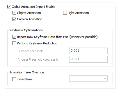
Object Animation
If checkmarked, object animation is imported from the FBX file. Supported fcurves are: explicit location, explicit scaling and explicit rotation.Camera Animation
If checkmarked, camera animation is imported from the FBX file. Supported fcurves are: position (look-from), interest (look-at), roll and field-of-view.Light Animation
If checkmarked, light animation is imported from the FBX file. Supported fcurves are: position (shine-from), orientation (shine-direction), interest (shine-at) and color.Keyframe Optimizations
Import Raw Keyframe Data from FBX (whenever possible)
If this checkbox is enable then this importer will import the keyframe data untouched, as it is defined in the FBX file. If it is not possible to import the keyframe data untouched then the fcurves will be resampled.If this checkbox is disabled then this importer will import the function curve animation channels from the FBX file and then resample them into explicit Bezier curves, with optional keyframe reduction applied to them.
Perform Keyframe Reduction
If this option is enabled then an algorithm will be applied to the new imported keyframe lists to reduce the number of redundant keys. The type-in values determine the threshold criteria for keeping or removing a key from a list.If this option is disabled then no keyframe reduction will be done. If you want very accurate animation import then do not enable this option, or else keep the threshold values at minimum values to keep the degree of reduction low.
Distance Threshold
This numeric value indirectly controls how many redundant keyframes are to be removed from the re-sampled keyframe list. Higher values will cause more keyframes to be removed. This value is the maximum distance the new keyframe list is allowed to deviate from the original re-sampled keyframe list. Take for example a sphere that is animated along a path; if this threshold value is set to 0.5 distance units then redundant keyframes of the animated path will be removed until such point that the sphere begins to deviate by more than 0.5 units from its ideal location. In other words, if the value is set to 0.5 then you are guaranteed that the new reduced keyframe list will move the sphere along the same path in space, except that the sphere is allowed to deviate by 0.5 units from its original path. Smaller numbers will make the sphere adhere closer to its original path, but at the expense of retaining more keyframes.Angular Threshold (degrees)
This is the same as the previous numeric value except that it applies to reduction of quaternion and Angle/axis rotation keyframe lists. The value is measured in degrees. For example, if set to 5.0 then redundant keyframes will be removed from a keyframe list until such point that a rotation angle begins to deviate from its ideal angle by more than 5 degrees. Small numbers (such as 1.0 and 0.5) will cause less deviation and more precise rotation conversions, but at the added expense of retaining more keyframes.Animation Take Override
A FBX file can contain zero or more "Takes" of animation. This list box selects the particular animation take to import. You can also enter your own Animation take name if you desire to import some specific animation take from file to file.