

| You are here: Home » Import CAD Formats » NGRAIN's 3KO Solutions |
Support: 905-672-9328 Copyright © 2026 Okino Toronto, Ontario, Canada. |
Okino's 3MF export conversion system intelligently and robustly converts from the worlds most popular and complex 3D programs (MCAD, AEC, DCC and VR/AR) into 3D Manufacturing Format (3MF) files for subsequent 3D printing.
The 3D Manufacturing Format (3MF) is a 3D printing file format spearheaded by Microsoft that allows design applications to send full-fidelity 3D models to other 3D applications, platforms, services and 3D printers. As explained by Microsoft, "3MF files describe the appearance and structure of 3D models for the purpose of manufacturing (3D printing)." It was primarily designed to replace the simplistic and aging 1987-era STL file format for 3D printing (as well as OBJ and VRML2).
History, features, overviews, implementation partners and more can be read on the 3MF Consortiums web site.
Microsoft Windows 10 uses the 3D Manufacturing Format (.3mf) file type for all 3D printing tasks.
Please also refer to the corresponding 3MF import converter.
- Accurate conversion from all sources of primary 3D data files, including MCAD, AEC, DCC and VR/AR software applications and file formats.
- Full geometry instancing support throughout the conversion pipeline from 3D file import to 3MF file export.
- Layered texture map support with automatic embedding and resizing of JPEG and PNG bitmap images. This exporter has a unique and intelligent method to determine how to deal with 3MFs oddities relating to layered texture images (see examples further below in this help).
- Conversion from all supported source 2D bitmap image file formats to embedded JPEG or PNG images within the 3MF file, of variable width/size and bit depth.
- Support for multiple layers of uv texture coordinates for each exported geometry object.
- Export of vertex colors and/or mixing of vertex colors with an objects surface (diffuse) color.
- Support for the 3MF Core Specification and the 3MF Materials Extension.
- Mesh processing options such as automatic polygon reduction, explode-by-material assignment, sort polygons by material and coordinate list optimizations.
- Multiple methods to embed pivot points in the geometry data.
- CAD-like units matching.
Click on any one of the small screen snapshots to jump to the corresponding section of this WEB page:
| Main | Selective # 1 | Selective # 2 |
|---|---|---|
![[1]](/conv/exp_3mf_main_sml.gif) |
![[2]](/conv/exp_3mf_selective1_sml.gif) |
![[3]](/conv/exp_3mf_selective2_sml.gif) |
| Materials | Bitmap Embedding | Image File Paths |
|---|---|---|
![[4]](/conv/exp_3mf_materials_sml.gif) |
![[5]](/conv/exp_3mf_bitmaps_sml.gif) |
![[6]](/conv/exp_3mf_filepath_sml.gif) |
This panel contains the 3MF export options which are most often used or should be considered during an export process.
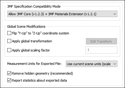
3MF Specification Compatibility Mode
Note: if the destination program cannot read in the 3MF file then reset this combo box to Restrict Output to 3MF Core Specification.Restrict Output to 3MF Core Specification
Choosing this combo box option basically restricts each mesh geometry object to have a single display color (and material name) and such a style attribute may be interpreted by the destination program/printer as "print this in yellow plastic", or "print this using copper".No texture mapping, uv texture coordinates or vertex colors are supported in this core mode. Hence, this is a rather restricted export model when it comes to material attributes and texture mapping capabilities.
Allow 3MF Core Specification + 3MF Materials Extension
Choosing this combo box option allows for extended material definitions to be output to the 3MF file. However, at the time of writing of this help documentation, few destination programs (which support 3MF) have been able to read and use such extended material definition information.This extended mode supports layered texture maps, uv texture coordinates, vertex colors and embedded JPEG/PNG bitmap texture images.
Global Scene Modifications
Flip "Y-Up" to "Z-Up" coordinate system
This option allows the default coordinate system to be set for the 3MF file. It defines what will be considered the "Up" axis in the exported 3MF file.Enabling this option will flip the source Y-up data of the internal Okino scene graph to the Z-up coordinate system of the exported 3MF file.
Apply global transformation
If this checkbox is enabled then a general purpose global transformation will be applied to each exported 3MF scene. This new transformation matrix will be applied to the root node in the exported 3MF file.
- Re-center all of the geometry so that it is centered at the origin (0,0,0) in the 3MF file.
- Move all of the geometry so that it is sitting on the Y=0 (XZ) horizontal plane.
- Auto-scale the geometry so that it is no larger than a specific bounding box size.
- Scale the scene by a (X, Y, Z) value.
- Shear the scene by a (X, Y, Z) value.
- Rotate the scene by a (X, Y, Z) value.
- Translate the scene by a (X, Y, Z) value.
The transformation can be edited by pressing the "Edit Transform" button which will cause the following global transformation dialog box to appear:
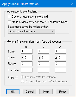
The transformation matrix will be computed in two phase: (1) the transformations specified in the top "Automatic Scene Resizing" section, then (2) the single transformation specified in the "General Transformation Matrix" section.
The values on the dialog box are described as follows:
Automatic Scene Resizing
Center all geometry at the origin
If this checkbox is enabled (checkmarked) then all the geometry data will be positioned so that it is centered about the origin. If disabled then the geometry will not be repositioned.Make all geometry sit on the Y=0 horizontal plane
If this checkbox is enabled (checkmarked) then the geometry will be repositioned so that it is sitting flush with the top of the Y plane (the horizontal plane).Scale geometry to be no larger than:
This option allows the geometry data to be automatically rescaled if it is too large. If set to 'Do not scale the geometry' then no scaling will be done. If set to '1x1x1 units' then all the objects will be scaled smaller should they exceed 1x1x1 units in total size. Likewise for the '2x2x2 units' option. If set to 'User defined maximum size' then the maximum size of all the objects can be set using the type-in numeric box. The default is '2x2x2 units'.Although not quite the same, if the option is set to Use Absolute Scaling Factor then all objects exported to the 3MF file will be scaled absolutely by the user specified value. Thus, if you set the type-in value to 0.25 then all objects will be made 4 times smaller and if the value if set to 4 then all objects will be scaled 4 times larger. This is useful is you are converting a variety of different models to 3MF format and you want them all uniformly scaled with the same scaling factor.
Transformation Matrix Values
Translate X, Y, Z
This applies a 3D translation by the specified amounts in the X, Y and Z dimensions.Scale X, Y, Z
This applies 3D scaling in the X, Y and Z dimensions. All 3 scale factors must be non-zero. Values above 1.0 will make the scene larger (2.0 will double the size of the scene) while values less than 0 will make the scene smaller (0.5 will half the size of the scene).Shear XY, XZ, YZ
This applies a linear shear in one of 3 directions:XY will shift all points in the X direction by the specified amount in proportion to the distance the points are located along the positive or negative Y axis. For example, using a value of 2.5 will shear all points by 68 degrees in the positive X direction; in other words, for every unit increase in the Y direction the X points will be shifted by 2.5 units.
XZ will shift all points in the X direction by the specified amount in proportion to the distance the points are located along the positive or negative Z axis.
YZ will shift all points in the Y direction by the specified amount in proportion to the distance the points are located along the positive or negative Z axis.
Rotate Around X Axis
Rotate Around Y Axis
Rotate Around Z AxisThis applies a rotation about the X, Y and/or Z axes. The rotation angle is restricted to the range -360 to 360 degrees. The angle of rotation is counter-clockwise when viewed from the positive to negative axis of rotation.Apply global scaling factor = #
This value allows a custom scaling to be applied to the overall exported scene. For example, if set to 10.0 then the entire exported scene (geometry, lights and cameras) will be scaled 10 times larger.Measurement Units for Exported File
This combo box determines how the internal scene units will be matched to those which 3MF can understand and accept. For example, if the internal scene is defined using "cm" but this combo box is set to "Scale scene to meters" then the 3MF file will be written to use "meters" and all geometry will be scaled 100 times smaller. The unit of measurement will be saved as the unit tag within the 3MF file. 3MFs default unit of internal measurement is mm but that does not affect this exporter option.Use current scene units (scale if necessary)
If this combo box option is chosen (which is the default) then the exported 3MF file units will be made the same as the internal scene units. If no match is possible then the exported file will use meters. The geometry of the exported scene may also be scaled larger or smaller in order to provide exact unit matching.Use current scene units (no scaling)
If this combo box option is chosen (which is the default) then the exported 3MF file units will be made the same as the internal scene units. If no match is possible then the exported file will be set to use meters. No scaling of the geometry will be made if there is no direct mapping of the internal units to the exported 3MF units as is done by the previous option.
Blindly set to inches (no scaling)
Blindly set to feet (no scaling)
Blindly set to millimeters (no scaling)
Blindly set to centimeters (no scaling)
Blindly set to meters (no scaling)
If any of these combo box options are chosen then the exported 3MF file units will be set to inches, feet, mm, cm or meters. No scaling of the geometry will be made. This simply overrides the "unit" tag inside the 3MF file.
Scale scene to inches
Scale scene to feet
Scale scene to millimeters
Scale scene to centimeters
Scale scene to meters
If any of these combo box options are chosen then the exported 3MF file units will be set to inches, feet, mm, cm or meters. If the current internal scene units is not the same as the chosen 3MF export units format then the exported geometry will be scaled larger or smaller so that the units will match.Remove hidden geometry (recommended)
If this checkbox is checkmarked then any internal geometry of the 3D scene marked as being hidden will be ignored during export to 3MF.Report statistics about exported data
If this checkbox is checkmarked then statistics will be output after the 3MF file has been exported, which looks like this:3MF Export statistics: Number of meshes = 3 Number of polygons = 16005 Number of mesh vertices = 8112 Number of vertex normals = 8120 Number of uv texture coordinates = 33686 Number of materials = 10 Number of texture maps = 8
Notes:
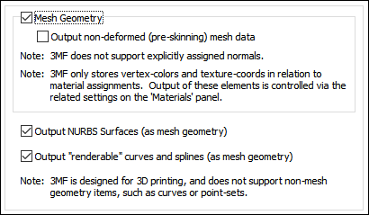
- 3MF is designed for 3D printing and does not support non-mesh geometry items, such as 3D curves, NURBS geometry or 3D point sets.
- 3MF requires that all mesh geometry be triangles and that they have a counter-clockwise order (when the triangles are viewed from the outside of the mesh object).
- 3MF does not support explicitly assigned vertex normals (smoothing information).
- 3MF only stores vertex colors and texture coordinates in relation to material assignments. Output of these elements is controlled via the related settings on the Materials panel.
Output Mesh Geometry
This checkbox should not, in general, need to be disabled. It controls whether polygonal mesh data will be output to the 3MF file.Output Non-Deformed (Pre-Skinning) Mesh Data
In the special case whereby your 3D scene uses skinned meshes (ie. polygonal meshes which are deformed by skeletons/bones) then this checkbox determines whether the original undeformed mesh is output or the post-bone-deformed mesh. If the checkbox is enabled then the original, pre-deformed mesh will be output.Output NURBS Surfaces (as mesh geometry)
This combo box determines whether trimmed NURBS geometry within the Okino database will be exported to 3MF as tessellated mesh data.Output Renderable Curves and Splines (as mesh geometry)
The Okino core software has an extensive 3D NURBS and Spline curve sub-system. Curves cannot be output to 3MF files but 3D mesh geometry can. If such curves form a closed boundary and are internally marked as "renderable" then they will be converted into a polygonal mesh object and then output to 3MF.
This panel controls the output of entities to the 3MF file.
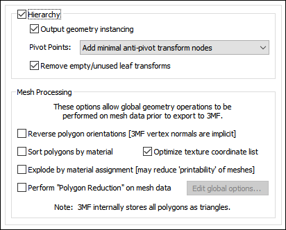
Output Hierarchy
If this option is enabled (checkmarked) then the hierarchical relationship of objects in the scene will be exported using nested 3MF nodes. If this option is disabled then no hierarchy will be output and all mesh objects will be exported in flattened world-space coordinates.Output geometry instancing (use instancing to reduce file size)
If this checkbox is checkmarked then the mechanism of "instancing" will be used to try and keep the size of the 3MF file as small as possible.In terms of 3MF lingo, the Printing3DcomponentWithMatrix object will be used to define instantiable geometry objects.
For example, if the source scene has 1000 bolts all derived from the same mesh primitive data, and the 1000 items have been placed in the Okino scene graph via "instancing" then during export to 3MF only a single copy of the geometry mesh data will be exported to 3MF, but with 1000 virtual copies made of it. These virtual copy instances merely act as indexes to the original mesh primitive data instead of being full copies, which can significantly reduce the size of the final output.
If this checkbox is disabled then unique and explicit copies of mesh data will be output to the 3MF file regardless of whether each copy is exactly the same as previous copies already exported.
Note: if a geometry items is instance two or more times, and each instance uses a different material/texture, then those geometry items will have to be explicitly duplicated into the 3MF file. In other words, instancing is not possible (to save file space) when such instanced items have different material/texture assignments.
Pivot Points
Pivot points are a fundamental component of an animation system. In the realm of the Okino animation system pivot points define a local 3D coordinate system in the space of an object about which the scale, rotation and translation animation function curves will be applied. The pivot point in Okinos scene graph is defined by a 3D point in space and a local coordinate system defined by 3 orthogonal XYZ axes; the pivot point is itself defined relative to the local coordinate system of the underlying mesh or geometry data.For example, the virtual pivot point and its orientation axes allow a robot arm to properly rotate around its elbow joint instead of some other awkward point of the object. Any such animation placed on the robot arm will then naturally occur relative to this elbow joint.
A basic problem is that not all destination animation programs have the same concept of pivot points as with a source animation program. Some programs are more complex, some much simpler. The following options control how Okino software performs this mapping.
First, some rules need to be defined for the following explanations. Pivot point processing only needs to be done under these circumstances for the two Minimal modes:
1) The pivot point 4x4 matrix has a non-zero origin or non-aligned orientation axis. In other words, it has something interesting in it, or
2) The instance has animated channels associated with it, or
3) The (static) transformation matrix associated with an instance has off-axis scaling within it. Off-axis scaling is where rotation comes before scaling, which is basically an illegal or poorly supported situation for most 3D programs.For a grouping folder (an Okino empty instance), which is deemed to have a valid pivot point matrix, a new child anti-pivot node is added to the exported hierarchy tree - the child node is assigned the inverse pivot matrix and the original parent transform node gets the animation data. This properly applies the anti-pivot effect to the subsequent children in the tree.
The following options specify how the Okino pivot point information is exported for instance-geometry nodes:
Embed minimal pivots in geometry data
Logic same as the next option below except that the processing mode will only be invoked when one of the 3 rules explained above are valid. This leads to a cleaner conversion.Embed pivots in *all* geometry data
Logic regardless of the 3 rules explained above, this processing mode will be invoked on ALL instance-geometry nodes if any of them have a non-identity pivot matrix.The inverse pivot matrix is multiplied into the raw mesh geometry vertices. In other words, the messy pivot point problem is made to disappear by having its 4x4 matrix physically multiplied into the mesh geometry vertices.
Add minimal anti-pivot transform nodes
Logic same as above except that the processing mode will only be invoked when one of the 3 rules explained above are valid.This is the default option since (1) it results in the fewest changes to the output hierarchy tree and (2) it does not physically affect the mesh geometry coordinate data.
Output all anti-pivot transform nodes
Logic regardless of the 3 rules explained above, this processing mode will be invoked on ALL instance-geometry nodes if any of them have a non-identity pivot matrix.A new "anti-pivot" dummy node is introduced into the exported hierarchy tree, between the mesh geometry object and the parent transform node (which has the animation on it). The inverse of the Okino pivot point matrix is assigned to the transformation matrix of this new anti-pivot dummy node. This new anti-pivot node acts to pivot-in the geometry vertices prior to the animation data being applied to the geometry.
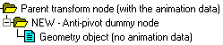
Thus, this mode splices in the pivot point matrix into the destination hierarchy tree as a new transformation node rather than to multiply the pivot point matrix into the raw mesh geometry, as with the other modes.
Ignore all pivot point data (can cause problems)
This option prevents pivot point information from being output to the 3MF file. Normally you would never want to enable this option.Remove empty/unused leaf transforms (empty grouping nodes)
If an exported NULL/grouping node has no children, is not a joint of a bone hierarchy and has no animation on it, then such useless grouping/NULL nodes are deleted during the export process if this checkbox is enabled..If this option is disabled then such useless grouping/NULL nodes are retained during the export process into 3MF and not deleted. You will want to disable this checkbox if you are exporting a file of NULL nodes and you wish all of them to be exported without pruning.
Mesh Processing
These options allow global operations to be performed on mesh data prior to export to 3MF.Reverse (flip) polygon orientations [3MF vertex normals are explicit]
If this option is enabled (checkmarked) then the orientation of all polygons will be reversed. For example, if the vertex normals of the object currently all face inward then this function will cause all of the vertex normals to face outward, and cause the orientation of each polygon to flip between clockwise and counter-clockwise.Sort polygons by materials
Checkmark this checkbox to cause the order of the polygons in the processed mesh data to be sorted according to the names of the material (surface definitions) assigned to them. Normally the polygons are output in the same order in which they exist internally in the database. However, some scenes may benefit from fewer material state changes from one polygon to the next, so enabling this option will cause the polygon order to be changed so that each run of polygons will only use the same material assignment.Explode by material assignment [may reduce printability of meshes]
Checkmark this checkbox to cause each mesh object to be exploded by the assigned material definitions. One or more meshes will be output to the 3MF file in succession, each using a different material assignment.Optimize texture coordinate list
Checkmark this checkbox to have the any duplicated uv texture coordinates removed.Perform "Polygon Reduction" on mesh data
If this checkbox is enabled (check-marked) then the 3MF exporter will apply the global polygon reduction algorithm to each mesh object just prior to them being embedded in the 3MF file.The algorithm allows the number of polygons in the scene to be greatly reduced. The parameters used to reduce the polygons can be modified by pressing the "Edit Polygon Reduction Global Options" button. Press the "Help" button on its corresponding dialog box to learn more about the polygon reduction system.
Materials and texture maps are assigned to mesh objects in 3MF files via material definitions. This panel controls the output of the material definitions, their associated texture maps, and provide fine grained control over the tweaking and modification of each 3MF material property.!! NOTE !! if an exported scene has its texture maps looking too bright or washed out then try this suggestion:
- Enable the "Merge and mix ambient color into diffuse color" checkmark option. Then manually disable or delete the default ambient light inside of 3MF.
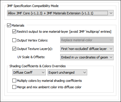
3MF Specification Compatibility Mode
This combo box is duplicated from the Main Options Panel.In order to allow for the export of layered texture maps, uv texture coordinates, vertex colors and embedded JPEG/PNG bitmap texture images you will need to set this combo box to 3MF Material Extensions; however by doing so, at the time of writing of this help documentation, few destination programs (which support 3MF) have been able to read and use such extended material definition information.
Output Materials
If this checkbox is checkmarked then extended materials will be exported to the 3MF file.If this checkbox is uncheckmarked then only a single Display Color per mesh object will be output to the 3MF file.
Restrict Output to One Material-Layer (avoid 3MF multiprop entries)
The 3MF Material Extension allows for mutli-prop entries which in turn allows for 1 or more layered textures to be associated with one 3MF material. However, it has been found that such a material extension has not been supported well by destination 3MF enabled programs.The 3D Print application will show multi-layered texture maps if its print-material option is set to MultiColor+.
Note: the 3MF Material Extension does not provide any control over how much one texture layer is mixed/blended into the prior layer. This seemingly is only handled by the intensity of the alpha channel on the subsequent texture map layer.
Output Vertex Colors
If this checkbox is checkmarked then an explicit vertex color will be exported along with each mesh geometrys vertex.Note: vertex colors are not too common for the general source 3D files which you may come across. Vertex colors have always been a fundamentally supported aspect of all Okino 3D import and export converters but they need special attention when sending to a destination exporter.
Replace Material-Color
If this combo box option is chosen then the vertex colors, which may exist along with each of the vertices of the source mesh data, will be explicitly output, verbatim, to the 3MF file.Blend with Material-Color
If this combo box option is chosen then the vertex colors, which may exist along with each of the vertices of the source mesh data, will be written out to the 3MF file after they have been multiplied by the source materials diffuse surface material color. In other words, the surface color of the original material assigned to the mesh geometry will be multiplied into each exported vertex color. In this manner youll get the best of both worlds, so to speak, by having a portion of the vertex color and a portion of the original surface material color showing up on the exported mesh geometry model within the 3MF file.Output Texture Layer(s)
If this checkbox is checkmarked then 1 or more layers of 2D texture maps that have been assigned to the material definition(s) will be exported to the 3MF file.Note: 3MF allows for the use of a different set of uv texture coordinates for each layer and that is supported by this exporter.
Which Texture Layers to Output (combo box)
The following combo box options may be confusing without some prior explanation. 3MF allows for multiple layers of texture maps to be applied to a single object but it does not allow for an explicit mix parameter to be specified which defines how much a new layer is mixed/multiplied into the prior texture layer. Rather, this exporter uses the 3MF mix mode which uses the alpha channel of each layer to define how much each texel of the current layer is to be mixed with the prior layer during realtime rendering:Final color = previousLayerColor * (1 - newLayerAlpha) + newLayerColor * (newLayerAlpha)
A consequence of this mixing mode is that any 100% opaque (non-transparent) texture layers are going to completely override/occlude any prior layers. It will only be a texture layer which has an alpha channel for which mixing will occur with each prior layer and at rendering runtime.
As a result this exporter is set up to examine the transparency of all texture-layers, and decide which ones are 'opaque' vs 'transparent'. Anything "below" the topmost 'opaque' texture will be considered to be "occluded" (as 3MF would not display it). Any 'transparent' (decal) layers "above" the topmost 'opaque' layer can also be safely exported (so long as we are not restricting output to a single-layer).
Note: you will most likely want to use either of the two Non-occluded modes, as they are designed to provide the "most correct" visual representation (given the limitations of the 3MF file format). The other modes are more or less included as workarounds when they not achieve what is desired.
Before explaining each of these modes, lets look at a contrived example of 4 diffuse texture maps layered on top of each other. Layers 3 and 4 are semi-transparent (due to them being alpha channeled decals) and hence can be considered non-occluders. However, layer 2 fully occludes (hides) layer 1 since brick2.jpg has no transparency in its alpha channel.
- Layer 1 -- "brick.jpg" (100% opaque)
- Layer 2 -- "brick2.jpg" (100% opaque)
- Layer 3 -- "logo.png" (decal, semi-transparent)
- Layer 4 -- "frame.png" (decal, semi-transparent)
Last (Topmost) Diffuse Texture Layer Only
Layer 4 -- "frame.png"First (Lowest) Diffuse Texture Layer Only
Layer 1 -- "brick.jpg"All 'Non-Occluded' Diffuse Texture Layers
Layers 2 through 4 -- Generates a 'multiprop' in 3MF with texture-layers "brick2.jpg", "logo.png" and "frame.png".First 'Non-Occluded' Diffuse Texture Layer Only
Layer 2 -- "brick2.jpg" because it 100% occludes (hides) layer 1.All Diffuse Texture Layers
Generates a 'multiprop' in 3MF with texture-layers "brick.jpg", "brick2.jpg", "logo.png" and "frame.png". (This is potentially wasteful -- the "brick2.jpg" will overwrite any color-contribution provided by "brick.jpg", according to 3MF rules.)All Diffuse Texture Layers
This combo box option is only available when the Restrict Output to One Material-Layer checkbox is disabled.It will output all texture layers regardless of whether they may occlude the prior texture layer (see the explanation further above).
Last (Topmost) Diffuse Texture Layer Only
As per the explanation above, this combo box option outputs the top-most diffuse texture layer.Since there is no expressed and controllable mixing between texture layers in 3MF it only makes sense to output the top-most opaque layer only.
First (Lowest) Diffuse Texture Layer Only
For the same of completeness, this outputs the first and lowest texture layer. In general you may not want to use this option.All Non-Occluded Diffuse Texture Layers
As per the explanation above, this combo box option outputs all texture layers which this exporter deems as having some means of mixing together with each other at rendering time (the exporter will examines the RGBA texture images on disk to see whether any of them contain transparency in their alpha channels).In other words, this exporter will output the texture layers which have some alpha-channel-based mixing happening between them and the base-level 100% opaque layer from which the mixing will start.
In the example above, Layer 2 fully occludes layer 1 and hence layer 2 is considered the base layer. Layers 3 and 4 have some mixing happening due to their transparency alpha channel (since they are considered to be decals).
First Non-Occluded Diffuse Texture Layer Only
This is the default combo box option.It will output the lowest texture layer which was found to completely occlude (hide) all lower layers. For the example above, that is layer 2
UV Scale & Offsets
Each texture map reference used in an Okino material allows for the texture map to be scaled and offset in "UV space". This combo box determines how this scale and offset information is output to the 3MF file.Do not output (ignore)
The information is not output. You would normally not want to use this option since the applied textures will look wrong if any of them have scaling or offsetting.Embed in uv Texture Coordinates of Geometry
The texture's UV scale and offset values will be multiplied into the uv texture coordinates of each exported mesh geometry object to the 3MF file.Shading Coefficient and Colors Overrides
These combo boxes provide hands-on control over how exported material shading parameters should be modified so that the exported model can be rendered nicely as it would have looked in the source 3D program. The two combo boxes and the single numeric text box provide you good control over the ambient, diffuse, specular, opacity and shininess shading coefficients exported to 3MF.The first drop-down combo box selects which of these shading parameters is to be modified. Each shading coefficient has its own operation that can be selected (via the second combo box) and an optional numeric text value (via the third data entry text input box). The following describes the various shading parameters that can be controlled:
Ambient Coefficient: This controls the amount of color reflected from an object based on the ambient light in a scene. A good default value is 0.1 through to 0.3 and ideally ranges from 0.0 to 1.0.
Diffuse Coefficient: This controls the amount of color reflected from an object based on the direct light shining on it. A good default value is 0.4 and ideally ranges from 0.0 to 1.0.
For each material shading parameter, several actions can be performed on each material shading parameter during the import process:
Do Not Export: When this option is selected, the shading parameter is set to 0, effectively making the shading channel appear black (for color channels).
Export Unchanged: When this option is selected, the shading parameter is exported as is, with no change.
Set and Use Default: When this option is selected, the shading parameter is set to some "good" default value (as determined by the export converter). This default value will be displayed in the input text box.
Set to Specific Value: When this option is selected, the exported shading parameter will be overridden with the user specified value of the numeric input text box.
Export and Crop by: When this option is selected, the shading parameter is exported and will remain unchanged if it is less than the numeric text input value shown on the dialog box. If it is greater, then the exported value will be clamped to be no greater than the numeric type-in value. This is a good operation, for example, if you do not wish for the ambient shading coefficient to be greater than 0.3.
Export and Scale by: When this option is selected, the shading parameter is exported and multiplied by the numeric input text value shown on the dialog box
Multiply colors by material shading coefficients
Inside Okino's internal scene graph each material has a "color" and a corresponding "shading coefficient" for each ambient, diffuse and specular color definition. The "shading coefficient" can be considered a variable intensity control that brightens or darkens its corresponding color, without having to modify the color itself.If this checkbox is checkmarked then each shading coefficient is multiplied into its corresponding color value before being exported to the 3MF file material. Normally you would want this option enabled as it creates a 3MF material definition which is very close in appearance to an Okino material definition.
If this checkbox is not checkmarked then only the raw colors will be output to the 3MF file and their corresponding shading coefficient values will be ignored. This will typically result in brighter, bolder and punchier materials, what we ourselves term "OpenGL" shading which tends to be more saturated than colors seen in photo-realistic rendering programs.
Merge and mix ambient color into diffuse color
Enabling this checkbox will cause the materials ambient color to be mixed into the diffuse material color before the final diffuse color is exported. Disabling this checkbox will not output any ambient material color.
The 3MF file format only allows for texture bitmaps to be embedded in the .3mf file and does not allow for external references to bitmap images on disk. In addition, 3MF only allows for JPEG and PNG bitmap files to be embedded within the file. Hence, this panel determines which of these two bitmap image file formats are to be used.
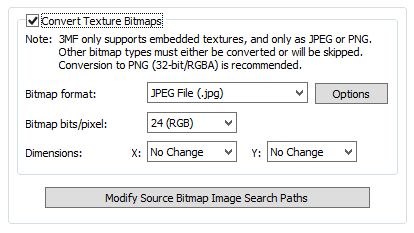
Bitmap File Format (Combo Box)
This combo box determines whether the bitmap image will be embedded within the 3MF file as a JPEG or PNG file.Bitmap Bits/Pixel: 2, 4, 8, 24 (Combo Box)
This combo lists determine the number of bits/pixel to write out to the embedded bitmap file. The default is 24 bits. A color quantization algorithm will be used for the 2, 4 and 8 bits/pixel output formats.Dimensions: X = #, Y = #
These two drop-down list boxes determine the X and Y resolution for the converted bitmap file(s):
No Change = Do not change the X or Y size Closest = Use the next highest power-of-2 size 2, 4, 8, ... 256, 512 = Choose a specific size for the X or Y dimension Modify Source Bitmap Image Search Paths
In specific circumstances it may be necessary to inform the 3MF exporter where your source bitmap images are located so that the image embedding process can locate and load the images.If the 3MF exporter reports warnings that specific images could not be located during automatic bitmap conversion or embedding, then press this button so that the Search-Paths dialog box appears. Using this dialog box you can inform the 3MF exporter where the source bitmaps are located.
If a texture bitmap file reference is to be added to a 3MF file then this panel controls what will be done to the file path of that image filename.
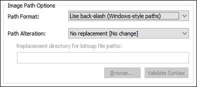
Path Format Combo Box
This combo box determines what kind of file path format will be used.Use back slash (Windows-style paths)
If this option is chosen then all bitmap file paths written to the file will be converted to a Windows/DOS compatible format. In particular, directory separators will be converted to backward slashes \.Use forward slash (Unix-style paths)
If this option is chosen then all bitmap file paths written to the file will be converted to a UNIX compatible format. In particular, all Windows and DOS specific backward slashes \ will be converted to UNIX forward slash / directory separators.Also, any DOS-like drive specifiers, such as c:\ will be removed from the file path and a warning message will be reported indicating of the removal of this drive specifier (it should be ensured that all DOS-like drive specifiers are replaced by UNC specifiers, such as \\machine1\).
Use the RFC 1738 Standard (URL paths)
If this option is chosen then all bitmap file paths written to the 3MF file will be converted into the "RFC 1738" URL format specification. This option is rarely needed and is provided in this exporter for convenience.As examples:
C:\polytrans\bitmaps\texture.tif --> file:///C|/polytrans/bitmaps/texture.tif
\\machine\polytrans\bitmaps\texture.tif --> file:////machine/polytrans/bitmaps/texture.tif
Path Alteration
In most 3D graphics programs and file formats a texture map reference is defined as a relative or absolute disk-based directory path which is appended with the name of the bitmap texture map + its file extension, such as c:\files\textures\bitmap.jpg. This combo box and its options allow the directory path to be stripped or replaced with something new.No replacement (no change)
If this option is chosen then the file path and texture bitmap image reference will not be changed.Strip file paths from all bitmap references
If this option is chosen then any file path on a bitmap image reference will be stripped off. For example, "C:\polytrans\bitmaps\texture.jpg" will be output as "texture.jpg".Replace file paths in all bitmap file references
This option allows all exported bitmap references to be prefixed with a new file path. This might be useful, for example, if all of the bitmap files are located in one specific directory or if you wish to change the prefix on the exported bitmap references.To choose the new file path press the Browse button.
If the Use the RFC 1738 Standard (URL paths) option has been chosen from the Path Format combo box, then the type-in edit box will instead contain the new RFC 1738 compliant URL and not a directory path. This user-entered URL will be used to prefix the bitmap image reference.
For example, if an original texture map references the filename:
c:\files\textures\bitmap.tifand the new URL is specified on this dialog box as:
http://www.okino.com/images/then the bitmap filename will be stored in the file as:
http://www.okino.com/images/bitmap.tif