| You are here: Home » Import CAD Formats » AutoCAD-Revit-Navisworks (DWF-3D) |

Okino's 3MF importer reads in 3D scene data from the industry standard 3D Manufacturing Format (3MF). Normally these files are used to export into 3D printing hardware devices but this importer was written as a means to read in and convert such 3MF files to other 3D software programs.
The 3D Manufacturing Format (3MF) is a 3D printing file format spearheaded by Microsoft that allows design applications to send full-fidelity 3D models to other 3D applications, platforms, services and 3D printers. As explained by Microsoft, "3MF files describe the appearance and structure of 3D models for the purpose of manufacturing (3D printing)." It was primarily designed to replace the simplistic and aging 1987-era STL file format for 3D printing (as well as OBJ and VRML2). It is human readable and saved in a XML encoding.
History, features, overviews, implementation partners and more can be read on the 3MF Consortium’s web site.
Microsoft Windows 10 uses the 3D Manufacturing Format (.3mf) file type for all 3D printing tasks.
Please also refer to the corresponding 3MF export converter.
Click on any one of the small screen snapshots to jump to the corresponding section of this WEB page:
| Selective-1 | Selective-2 | Units Matching | Materials |
|---|---|---|---|
![[1]](imp_3mf_selective1_sml.gif) |
![[2]](imp_3mf_selective2_sml.gif) |
![[3]](imp_3mf_units_sml.gif) |
![[4]](imp_3mf_materials_sml.gif) |
- 3MF is not a 3D data inter-change file format whatsoever. Hence, please do not choose the 3MF file format to convert from one 3D application to another. It is primarily made as a one-way file format into 3D printing devices and related software applications.
- 3MF does not support explicit vertex normals which is otherwise a staple of most 3D file formats.
- There is no support for camera, lights, skinning/skeletons, animation data, etc. In simple terms, 3MF is the newer cousin of the STL file format. STL itself is the world’s simplest of simplest 3D file formats and not some complex CAD file format as many 3D users have come to wrongly believe.
- Reading of 3MF supported polygonal geometry, part names, part hierarchy, basic material properties, layered texture maps and the extraction of JPEG+PNG bitmap images. Geometric and vertex normals will be computed for geometry without such information.
- Respect for, and the import of, geometry instancing, including 3 Okino scene and hierarchy optimizers.
- Layered texture map ("multi-property material") support with automatic extraction of JPEG and PNG bitmap images.
- Import of vertex colors.
- Intelligent overrides for the material colors and coefficients, to create "load and render" files.
- Support for the 3MF Core Specification and the 3MF Materials and Properties Extension.
- CAD-like units matching.
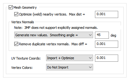
Mesh Geometry
If this checkbox is checkmarked then mesh geometry will be imported from the 3MF file. Normally you would always want to keep this option enabled.Optimize (weld) nearby vertices. Max distance = #
This function will delete all redundant vertices from the polygonal mesh geometry which are within a specified distance of each other. The default distance is shown on the dialog box. This option is enabled by default so that the imported 3MF mesh geometry is more refined and “welded” together. Most destination 3D programs will expect the mesh geometry to be in this refined, welded format.Vertex Normals
Vertex normals are used to specify where an object is to appear smooth and where it is to appear faceted (rough).Combo Box:
This combo box determines what is to happen to the vertex normals during the import process:Do Not Import
No vertex normals are imported. The resulting polygonal meshes will appear “faceted” in the destination 3D program.Generate New Values. Smoothing angle = #
Brand new vertex normals will be automatically generated based on a “smoothing angle”. This is the default because 3MF files do not contain any vertex normals information.The vertex normals are computed based on the angle between abutting polygons. If the angle between the geometric surface normals of abutting polygons is less than the 'Smothing Angle' type-in value (in degrees) then newly computed vertex normals will be assigned to the polygons (they will be smoothed). Higher values make the object appear to be smoother and have less sharp corners (such as 40 to 60 degrees).
Remove Duplicate Vertex Normals. Max diff = #
This is the same as the 'Optimize (weld) nearby vertices' function except that it combines redundant normals that are within a certain threshold of each other. It can make for more optimized imported meshes and possibly smaller files.UV Texture Coordinates:
UV texture coordinates are a vital aspect of 2D bitmap image texture mapping. They are 2D values associated with a 3MF polygonal mesh object which defines how a planar bitmap image is to be draped over top of the mesh. This combo box determines what will be done to those texture coordinates during the 3MF import process.Do Not Import
No vertex texture coordinates are imported. The resulting polygonal meshes will not be texture mapped as a result.Imported (Unoptimized)
The original 3MF vertex texture coordinates will be imported as-is.Import + Optimize, Tolerance = #
The original 3MF vertex texture coordinates will be imported as-is but also any redundant coordinates will be deleted based on the threshold value shown on the dialog box (any texture coordinates within a threshold of that value from each other will be welded into a single coordinate value, thus making the imported data more optimized and possibly smaller in size).Vertex Colors:
Vertex colors were somewhat more common in 3D file formats (like OpenFlight) back in the 1980s and 1990s before realtime 3D texture mapping became more prevalent. They allow explicit RGB colors to be associated with each mesh vertex. This combo box determines what will be done to those vertex colors during the 3MF import process.Do Not Import
No vertex colors are imported.Imported (Unoptimized)
The original 3MF vertex colors will be imported as-is.Import + Optimize, Tolerance = #
The original 3MF vertex colors will be imported as-is but also any redundant colors will be deleted based on the threshold value shown on the dialog box (any vertex colors within a threshold of that value from each other will be welded into a single RGB color value, thus making the imported data more optimized and possibly smaller in size).Flip Model so that 'Y' Axis is 'Up'
By default the data is imported so that the 'Y' up axis in the 3MF becomes the 'Y' up axis in Okino software. If this checkbox is enabled, then the imported data will be reoriented so that the 'Z' axis in the 3MF file becomes the 'Y' Up axis in Okino software. In other words, this option flips the imported model by 90 degrees.
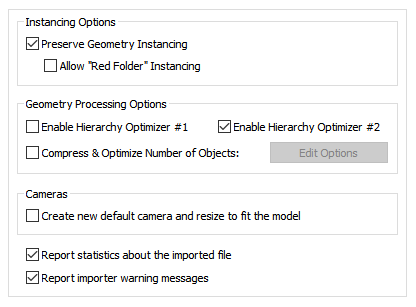
Instancing Options
Preserve Geometric Instancing
If this checkbox is checkmarked then the mechanism of "instancing" will be used to try and keep the size of the imported 3MF file as small as possible. For example, if the source file has 1000 bolts all derived from the same mesh primitive data, and the 1000 items have been placed in the 3MF file via "instancing" then only a single copy of the geometry mesh data will be imported, but with 1000 virtual copies made of it. These virtual copy instances merely act as indexes to the original mesh primitive data instead of being full copies, which can significantly reduce the size of the final output.If this checkbox is disabled then unique and explicit copies of mesh data will be imported from the 3MF file regardless of whether each copy is exactly the same as previous copies already imported.
Allow “Red Folder” Instancing
This checkbox is particular to Okino software. Okino software has the notion of a “red grouping folder”. It is an extended geometric instancing method whereby entire sub-hierarchies can be cloned/instanced easily. For example, if the red folder contains various parts to make a chair (the seat and 4 legs) then any number of copies of the chair can be made, without explicit geometry duplication, by creating instances of this red folder. Hence, this option is an optimization for importing 3MF files where this mechanism determines that red folder instancing can be best utilized.Geometry Processing Options
Hierarchy Optimizer # 1, Hierarchy Optimizer # 2
These options provide methods to remove redundant hierarchy nodes (“NULLs”, or grouping folders) from the imported file. Optimizer #1 removes runs of empty folders, as well as folders with no children. Optimizer #2 is simpler, deleting empty folders which only have 1 geometry object in them. These options can also be enabled via the “Optimize hierarchy after completion” checkbox found on the options dialog box of the “Compress & optimize number of objects” option (see below).Compress & optimize number of objects
This checkbox enables one of the most important and critical scene processing functions in all of Okino software. It is an integral and core part of any Okino CAD converter, and it has been added to the 3MF importer for added benefits.The primary purpose of this function is to walk the imported geometry hierarchy and compress together all objects that are parented under a single folder into a one new object. For example, if you have a scene with 200 parts that are grouped under one assembly node then enabling this option will cause all such occurrences to collapse the children geometry of each imported assembly node into one object definition.
The documentation for this option can be viewed by pressing the "Options…" button and then the "Help" button on the optimizer's dialog box.
Cameras
Create New Default Camera and Resize to Fit the Model
If this checkbox is enabled then a brand new Okino-specific 3D perspective camera will be created and made the “default” camera. The camera will be arbitrarily zoomed out to view the entire imported 3MF model. If this option is disabled then no new 3D perspective camera will be created.Report Statistics about the geometry file
If you enable this checkbox, statistics about the imported 3MF file will be displayed in the console.Report Importer Warning Messages
This will print all warning messages to the importer's console. A warning does not necessarily mean that any degradation of data has occurred or that an error has occurred.Note that deselecting this option will only cause warnings to be suppressed, not statistics or errors. If there is an error that would cause the importer to abort, then this is printed to the console when the process is aborted regardless of whether or not the "Print Warning Messages" option has been checkmarked.
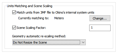
Units Matching and Scene Scaling
Match units from 3MF file Okino's internal system units
These options determine what will be done when the units defined in the current 3MF scene do not match those of the destination Okino “internal system units” (which is listed on the dialog box as the “Current matching to” units).If the units do not match then the importer will rescale the imported geometry based on the ratio between the 3MF units and the current Okino internal system units (the “Current matching to” units).
If this checkbox is enabled then the importer will rescale all imported geometry so that the units of the 3MF file will be made to match the current Okino internal system units. If the checkbox is disabled then the geometry will be imported unchanged and untouched, meaning that its scale may be "incorrect".
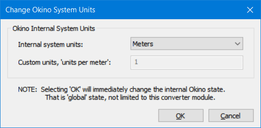
Internal System Units
This drop-down combo box specifies the current units system in effect within the internal Okino scene graph. It defaults to meters. What you need to do is select an appropriate entry from the drop-down combo box which matches the system units used by your destination program:
None No units; never do any geometry scaling Custom Custom units are in effect. See below Microinches 1e-6 inches Mils 1e-3 inches Inches 0.0254 meters Feet 12 inches Miles 63360 inches Microns 1e-6 meters Millimeters 1e-3 meters Centimeters 1e-2 meters Meters Kilometers 1e+3 meters Custom Units in "Units Per Meter"
If the drop-down "Internal System Units" combo box is set to "Custom", then this edit text control defines the "units per meter" scale factor for the custom unit system.Scene Scaling Factor = #
This option allows the imported scene to be scaled larger or smaller by a user specified amount.As examples, enter these values:
- 1.0, no scene scaling
- 1000, scale 1000 times larger
- 0.001, scale 1000 times smaller
- 4, scale 4 times larger
- 0.25, scale 4 times smaller
You can enter a value into the edit box specifying a relative scaling factor, and the model will be scaled by this factor. For example, if you enter '2.0', the model will come out twice as large.
Geometry automatic re-scaling method:
This combo box provides access to a useful mechanism which automatically rescales the imported geometry to a size best needed by other 3D software packages. This combo box can be used to automatically resize any imported model data to a useful size, such as scaled to easily fit inside a box of 2x2x2 raw working units. The various options are described as follows:Do Not Resize the Scene
No resizing is done to the imported data.Resize to 1x1x1 units
Resize to 2x2x2 units
The model data is automatically scaled up in size, or scaled down in size so that its world space extents fits inside a 1x1x1 or 2x2x2 sized unit cube.Resize to User Defined Absolute Size
The model data is automatically scaled up in size, or scaled down in size so that its world space extents fit inside a cube whose size is user defined by the type-in value shown on the dialog box. For example, if you enter the value 20 then the imported data will be resized so that its maximum extent in one or more dimensions is 20 units.Scale Larger by User Defined Factor
Scale Smaller by User Defined Factor
These options allow the imported model data to be scaled larger or scaled smaller by an absolute number. For example, if you select the ‘larger’ option and enter 10 into the type-in box, then the imported model will be scaled 10 times larger during the import process.
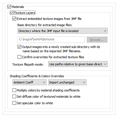
!! NOTE !! if an imported scene has its texture maps looking too bright or washed out then try this suggestion:
- Enable the “Set diffuse color of textured materials to white” checkmark option. This will set up better shading parameters for the final imported scene file.
Texture Layers
Extract embedded texture images from 3MF file
If this option is enabled then the texture maps embedded in the 3MF file will be extracted to stand-alone bitmap images on disk. If disabled, then no texture maps will be extracted and you will not see the model with applied textures.Note: The directory where the files are to be written must have write permissions.
Base directory to save extracted files
These combo box options define where the extracted texture map images will be written to disk.Directory where this program was executed from
The extracted images will be saved in the directory where this program began execution (which is usually the same as where this program is located on disk). This is not a preferable option since this directory will eventually become cluttered with images extracted from 3MF files.Directory where this 3MF input file is located
The extracted images will be saved in the same directory where the 3MF input file was read from. This is the default but in general it is recommended that the images be placed into a unique sub-directory, such as when the “Output Images into a Newly Created Sub-Directory” option is enabled.Directory Specified Below:
The extracted images will be saved in the directory indicated by the type-in edit box. If no directory is shown, or you want to change the current output directory, then the Browse button can be pressed to select the desired destination directory.Output Images into a Newly Created Sub-Directory With Its Name Based on the Imported 3DM Filename
If this additional checkbox is enabled then the newly extracted bitmap image files will be written into a new, unique sub-directory. The name of that new sub-directory will come from the name of the 3MF file being imported. The main parent directory location is set via the “Base directory to save extracted files” option above.You would want to enable this option if you are importing 2 or more 3MF files, as an example, and you do not want to have any filename collisions between them for the extracted texture maps. In other words, it may be possible that 2 different 3MF files will create the exact same extracted texture map files on disk, even though they have different contents – in this case the second file will cause the previous file’s texture maps to be overwritten unless we go and place them into their own unique sub-directories.
Texture Filepath Mode
Imported materials can have assigned 2D bitmap texture images (which itself is extracted from the 3MF file as a JPEG or PNG bitmap file on disk). By itself, that file will be referenced in the imported 3D scene by an absolute path to the directory where the file is stored and the filename itself.The following options determine what will be done to that absolute file path to make it more amenable to downstream use in any other destination program.
Use absolute paths to extracted textured textures
Choosing this option will retain the absolute file path, such as: 'C:\bitmap images\my textures\3mf_bitmap_image.jpg'Use paths relative to given base-directory
Choosing this option will modify the file’s path as per the one defined by the “Base directory to save extracted files” combo box. The resulting file path will be made relative and not absolute, such as: 'my textures\3mf_bitmap_image.jpg'Strip all paths, use filenames only
Choosing this option will only retain the root filename, such as: '3mf_bitmap_image.jpg'Shading Coefficients & Colors Overrides
These combo box options allow the various imported material attributes to be fine tuned or outright modified. The two combo boxes and the single numeric text box provide you good control over the ambient, diffuse, specular, opacity and shininess shading coefficients imported from the 3MF file.The first drop-down combo box selects which of these shading parameters is to be modified. Each shading coefficient has its own operation that can be selected (via the second combo box) and an optional numeric text value (via the third data entry text input box). The following describes the various shading parameters that can be controlled:
- Ambient Coefficient: This controls the amount of color reflected from an object based on the ambient light in a scene. A good default value is 0.1 through to 0.3 and ideally ranges from 0.0 to 1.0.
- Diffuse Coefficient: This controls the amount of color reflected from an object based on the direct light shining on it. A good default value is 0.4 and ideally ranges from 0.0 to 1.0.
- Specular Coefficient: This controls the intensity of the highlight color on an object. A good default value is 0.7 and ideally ranges from 0.0 to 5.0.
- Opacity: This is the inverse of transparency. 0.0 will make the object fully transparent, while at 1.0 the object will be fully opaque.
- Phong Shininess: This controls the width of the specular highlight seen on an object. An ideal range is 6 (very wide) to 300 (very narrow). The default is 32.
For each material shading parameter, several actions can be performed on each material shading parameter during the import process:
- Do Not Import: The shading parameter is not imported at all. No value is imported nor sent to the Okino software. Thus, the default material shading parameter value (as set inside Okino software) will be used instead.
- Import Unchanged: The shading parameter is imported as is, with no change.
- Set and Use Default: The shading parameter is set to some "good" default value (as determined by the import converter). This default value will be shown in the type-in box.
- Set to Specific Value: The imported shading parameter will be overridden with the user specified value of the numeric type-in box.
- Import and Crop by: The shading parameter is imported and will remain unchanged if it is less than the numeric type-in value shown on the dialog box. If it is greater, then the imported value will be clamped to be no greater than the numeric type-in value. This is a good operation, for example, if you do not wish for the ambient shading coefficient to be greater than 0.3.
- Import and Scale by: The shading parameter is imported and multiplied by the numeric type-in value shown on the dialog box
Multiply colors by material shading coefficients
Inside Okino's internal scene graph each material has a "color" and a corresponding "shading coefficient" for each ambient, diffuse, specular and luminous color definition. The "shading coefficient" can be considered a variable intensity control that brightens or darkens its corresponding color, without having to modify the color itself.If this checkbox is checkmarked then each shading coefficient is multiplied into its corresponding color value after being imported from the 3MF file.
If this checkbox is not checkmarked then only the raw colors will be imported from the 3MF file (ambient, diffuse, specular and luminous) and their corresponding shading coefficient values will be ignored. This will typically result in brighter, bolder and punchier materials, what we ourselves term "OpenGL" shading which tends to be more saturated than colors seen in photo-realistic rendering programs.
Set diffuse color of textured materials to white
This is one of those options that may come in handy for someone with particular requirements for their textured objects being imported from the 3MF file. If this checkbox is checkmarked then any material which has a diffuse texture map assigned to it will be imported in such a way that its underlying diffuse surface color will be set to white.This is useful because certain real-time renderers use an "OpenGL" shading model in which the diffuse color is multiplied into the assigned texture map colors - if the diffuse material color is dark or black then the texture map will not be visible (often a problem when exporting from Maya for which the diffuse surface color is always set to black for textured materials). Enabling this option will cause the diffuse surface color to become white, and thus it will not affect the brightness of the assigned texture map.
If this checkbox is not checkmarked then the diffuse surface color will be imported unchanged.
As noted at the start of this section of help file, this option can be enabled in case texture maps look too bright or washed out after being imported from the 3MF file (as one of two possible suggested methods).
Set specular color to white
If this checkbox is enabled then the specular material color will always be set to white (although, the white can be dimmed by changing the 'Specular Coefficient' material parameter override, as described above). If disabled, then the real material's specular color will be imported.

