

| You are here: Home » Import CAD Formats » NGRAIN's 3KO Solutions |
Support: 905-672-9328 Copyright © 2026 Okino Toronto, Ontario, Canada. |
|
The Okino "JT" export converter module allows various types of 3D geometry, hierarchy and materials (assembly data) to be exported to native .jt disk based MCAD files (otherwise called "DirectModel" files). The JT exporter is built upon the official "JT Open" toolkit which has been licensed from Siemens AG. The use of the official "JT Open" toolkit ensures consistency of JT files across the enterprise and throughout the PLM market.
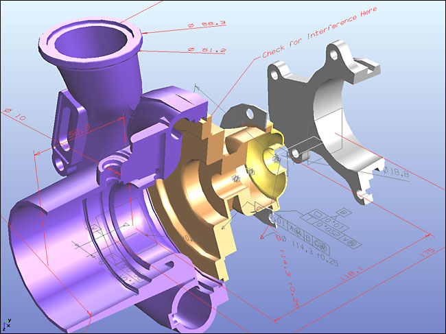
"NX Turbo-Charger" JT Model with PMI Data, imported from the JT-Open Showcase
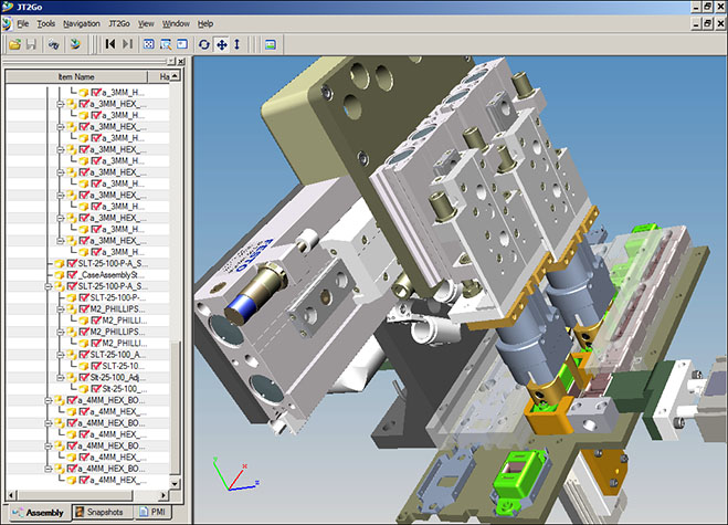
'Case Assembly' Converted & Optimized Directly From Solid Edge, Viewed in Jt2Go
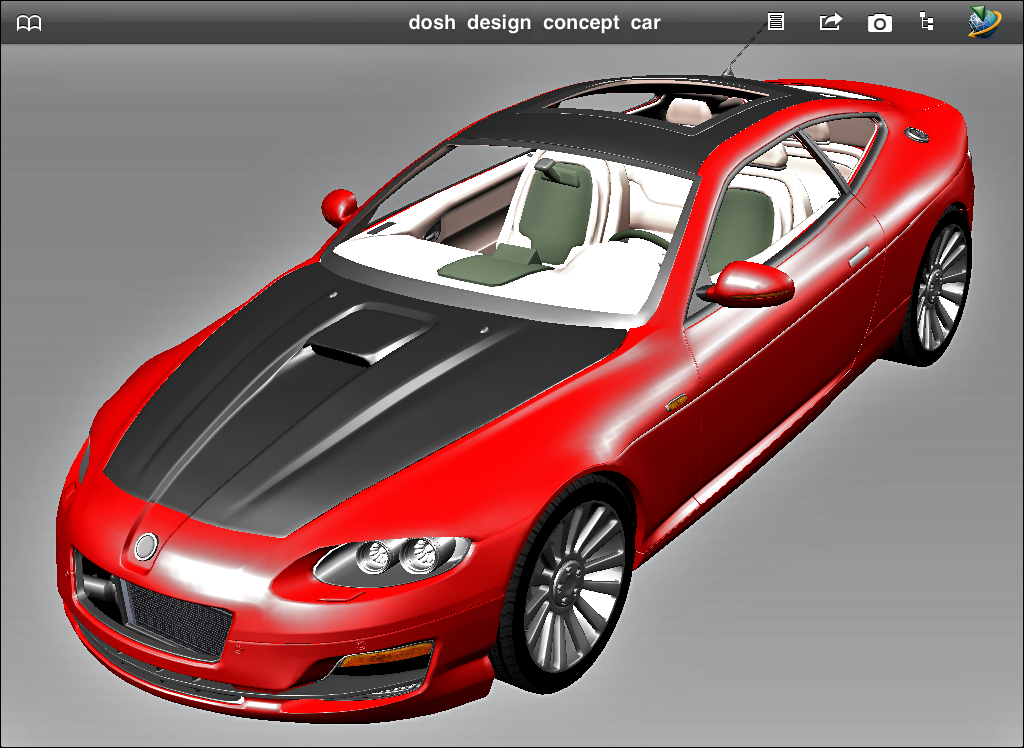
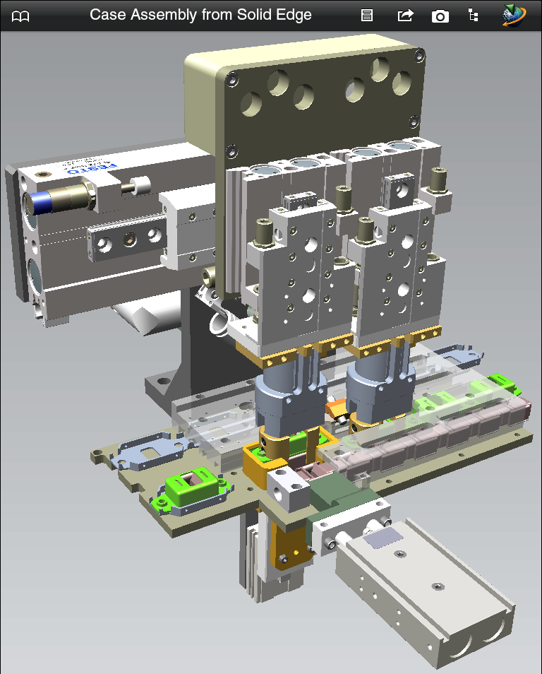
Dosch Design Concept Car (from Cinema-4D) & Case Assembly (Solid Edge), Viewed in Jt2Go iPad App
The corresponding JT importer online documentation can be found here.
The 'JT' exporter is sold as a seperate add-on module. It can be ordered online or directly by email/phone/fax ordering.
"JT" is the predominant and lightweight 3D visualization file format for PLM. It is in production use by thousands of companies worldwide. Compact and accurate, JT is used throughout the product development life cycle in all major industries to communicate the critical design information typically locked up inside a CAD file.
The JT data representation is:
- A rich data model with robust entity support.
- A high-performance, compact persistence archive format for graphics data.
- The best-in-class for supporting large assembly / model interactive capabilities.
- CAD-neutral supporting all major MCAD applications.
JT data can be very lightweight, holding little more than facet data or it can be richer and hold associations to the original CAD information, assemblies, product structure, geometry, attributes, meta data and PMI. It supports multiple tessellations and level-of-detail generation.
JT is a registered trademark of Siemens AG. All other brand names, product names or trademarks belong to their respective holders.
- "JT Open", http://www.jtopen.com. Main WEB site for the "JT Open" initiative
- "JT2Go", http://www.jt2go.com. View JT files via Microsoft Windows or iPad Viewer Apps.
Click on any one of the small screen snapshots to jump to the corresponding section of this WEB page:
| Main | Secondary |
|---|---|
![[1]](exp_jtsml1.gif) |
![[2]](exp_jtsml2.gif) |
| Geometry | Materials |
|---|---|
![[3]](exp_jtsml3.gif) |
![[4]](exp_jtsml4.gif) |
| Curves | Mesh |
|---|---|
![[5]](exp_jtsml5.gif) |
![[5]](exp_jtsml6.gif) |
| Bitmaps | File Paths |
|---|---|
![[6]](exp_jtsml8.gif) |
![[7]](exp_jtsml7.gif) |
- A plethora of options across 8 panels to provide you with great control over the JT scene export process.
- All main JT geometry types supported: NURBS surfaces, NURBS curves (exported as a BREP “wire” object), 3D polylines, 3D point sets and polygonal meshes with vertex normals, (u,v) texture coordinates and vertex colors.
- Automatic cross conversion of NURBS curves, spline curves and spline shapes into either JT NURBS curves or JT polylines. Control is provided through dialog box options. Closed curves marked as “renderable” can also be output as either trimmed NURBS surfaces or meshes.
- Exports point, spot and directional light sources and their related parameters. 18 predefined light configurations are made available, which allows lights to be automatically added to the exported JT scene if none are available in the source scene.
- Embedding of almost every possible 2D bitmap file format inside JT files (complete list of supported formats is listed on this Okino WEB page). If you do not wish to embed the 2D bitmap images, then support exists for automatic bitmap conversion to a desired 2D file format for file referencing from within the JT file.
- Material export including ambient/diffuse/specular/luminous colors, shading coefficients, associated diffuse texture map, opacity, Phong shininess and dozens of options to override or tweak any of these parameters prior to exporting.
- Export of "meta data" (JT object properties) information on JT nodes.
- Mesh geometry tweaking, modification and transformations via automated operations made available by Okino's suite of polygon reduction and transformation routines. Ideal as a means to "clean up" the source meshes and apply 80-95% pre-polygon reduction to the models prior to export to JT.
- Fine control over the JT compression methods used to take the polygonal mesh data and apply lossy or lossless compression techniques prior to file creation.
- Direct control over all of the major JT toolkit options used to create the final JT file.
This panel determines how the JT file will be "published". In particular it controls whether the exported data will be compressed (and how it will be compressed), the structure of the exported file(s), and whether BREP topology data will be output.
Compression level
JT files are often used for downstream visualization purposes. Large quantities of source data can be compressed into small JT files. This combo box determines which data compression scheme is used on the exported file.Automatic (use best JT file format version)
This causes the JT toolkit to select the best compression format. Usually this will be the newest file format version (version 8.x or newer).No compression (JT v6.4)
No compression will be made on the data. This will result in the largest file sizes. In general you can do better than having no compression.Lossless compression (JT v7.0)
This compresses the data with a dictionary loss-less technique (zlib-like).Lossless+lossy compression (JT v8.0)
This compresses the data with a dynamic selection of either a loss-less technique or a more advanced lossy compression scheme. This is the default since it provides the best compression levels.JT v9.0
Similar to JT v8.0, but of the newest supported version of JT.Enable advanced compression
This option is available when the currently chosen compression level is "Automatic" or "JT v8.0" (or newer). The "Advanced compression level" slider controls how aggressive the lossy compressor will work. Values near 0.0 will produce loss-less compression, while values approaching 1.0 will create much higher lossy compression.File structure
JT files are often written to disk as one root assembly file and multiple child .jt files. This combo box allows you to override the manner in which the JT files are written to disk.
Per-Part: one assembly file, many .jt part files
This writes one .jt root assembly file (containing the scene hierarchy) to disk which uses the same filename you had chosen for the exported JT data. A sub-directory will also be created with the same root name. That sub-directory will contain all the child .jt files that represent the parts in the scene (the geometry files will go into the sub-directory).Full Shattered: one .jt file per product structure
This is similar to "Per-Part" except that every node in the scene graph (ie. every hierarchy node in the assembly file) will be exploded into separate child .jt files, as well as all the geometry .jt files.Monolithic: one single .jt file
A single .jt file will be written to disk. This one file will contain both the assembly information and all the parts (the geometry).Mesh + BREP
JT files are often used for 2 main purposes:
- For the creation of "light weight" files for visualization purposes. These files mainly use polygonal data with high compression.
- For the creation of "precise" files that are used to convey NURBS surfaces between 2 CAD applications.
This combo box determines whether case (1), (2) or (1)+(2) are to be created.
Mesh data only
This outputs NURBS surfaces objects as JT tessellated meshes.BREP (NURBS surfaces) only
This will output NURBS surfaces to the JT file. No tessellation of the NURBS data will be done and no polygonal representations of the NURBS objects will be placed into the JT file.Mesh + BREP data
For a NURBS surface object, both a precise NURBS object and a tessellated (meshed) version will be written to the JT file.BREP data precision
This combo box determines the numeric precision of the NURBS data stored in the JT file. The default is "Double precision" which uses 64-bit floating point numbers. If file size is a concern then you could opt for "Single precision" which reverts to 32-bit floating point numbers (only 6 digits of precision).Enable BREP seam sewing
A "BREP" can be considered a container or one or more NURBS surfaces. In order to tessellate the NURBS surfaces to a polygonal mesh with no cracks between the seams the various NURBS surfaces need to be "sewn" together.Enabling this checkbox will cause all exported BREPs to have the JT sewing algorithm invoked. It is disabled by default because (1) it can be slow, (2) your BREP data may already be in a nicely sewn state, (3) Okino NURBS data is often independent NURBS surfaces.
The "Sewing tolerance" specifies the metric between which 2 vertices of a seam are to be considered shared, and hence sewn together. It is a percentage of the diagonal of each part's bounding box. The default is 0.001 (which is 0.1% of the bbox's diagonal).
If the final BREP does not appear properly sewn (ie. cracks appear in the tessellated mesh) then multiply the sewing tolerance in increments of 10 times.
This panel contains secondary options that affect the creation of the final JT file. In particular it controls some of the LOD (level of detail) JT options, and some other cursory exporter options.
LOD Generation
When mesh models are exported to JT files 3 "LODs" are automatically generated and added to the file. LODs are "level of detail" simpler representations. Each LOD is a progressively simpler and coarser meshed version of the main data.Enable extended part simplification for LODs
Enabling this option will cause JT to invoke decimation/simplification logic on tessellated geometry data to automatically populate the model with reduced level-of-detail (LOD) geometry. This can result in faster rendering at the expense of JT file size and tessellation time.Add 2 simple LODs: BBox + Shrink wrap
If this checkbox is enabled then an additional 2 LOD levels are added: (1) a simple box with the same extents as the base mesh, (2) a "shrink wrap" mesh model which represents the outer convex hull of the main base mesh.Smart LOD generation (add extra smooth levels)
This option enables a JT heuristic to "smooth out" a mesh part's LOD transitions by automatically generating and inserting new LODs to create a regular stride.Chordal LOD parameter interpretation:
This combo box determines how the internal LOD "chordal" value is used during the tessellation phase. The chordal values specifies how much the tessellated version of a BREP object is allowed to deviate from its meshed version (higher values results in coarser tessellations).Normally you would never want to modify this dialog box user option.
Relative (%age of part's bbox diagonal)
The chordal value is measured as a percentage of each part's bounding box diagonal. For example, a bolt is tessellated to the same degree as a larger part, and both have the same surface quality. This is the optimum setting.Absolute (global)
The chordal value is measured as an absolute distance. For example, larger parts are more tessellated than smaller ones.Verbose messages from JT toolkit
If this checkbox is enabled then addition warning or info messages are allowed to be output from the JT toolkit to the Okino message window.Do not write empty assembly and part nodes
Enabling this option will cause scene graph node pruning to occur. If an assembly node has no children, or a part has no geometry, then those nodes will be not be exported to the JT file.Output meta data
The JT file format allows for "meta data" information (JT "object properties") to be associated with each JT scene node.The following internal Okino scene graph meta data types are supported when exporting to JT: strings, shorts, ints, floats, colors, vectors, double precision vectors, 4x4 matrices, 4x4 double precision matrices, time, double precision floats, 4 valued vectors, and 4-valued double precision vectors. All numeric values will be converted into meta data string for output to JT.
Use geometry instancing to reduce file size
If this checkbox is checkmarked then the mechanism of "instancing" will be used to try and keep the size of the JT file as small as possible. For example, if the source scene has 1000 bolts all derived from the same mesh primitive data, and the 1000 items have been placed in the Okino scene graph via "instancing" then during export to JT only a single copy of the geometry mesh data will be exported to JT, but with 1000 virtual copies made of it. These virtual copy instances merely act as indexes to the original mesh primitive data instead of being full copies, which can significantly reduce the size of the final output.If this checkbox is disabled then unique and explicit copies of mesh data will be output to the JT file regardless of whether each copy is exactly the same as previous copies already exported.
This panel controls the output of geometric items (meshes, trimmed NURBS and 3D point sets), lights, and the addition of new pre-defined light configurations.
Output mesh data
If this checkbox is checkmarked then mesh geometry will be exported. This option also controls whether meshed versions of NURBS surfaces, bicubic patches, renderable NURBS curves or Spline Shapes will be output as well.Output vertex normals
If this checkbox is checkmarked then vertex normals will be exported along with the mesh geometry. Vertex normals are required to provide the "smoothing" information for a mesh model.JT file sizes can be made smaller by disabling vertex normals, but the exported meshes will look "faceted".
Reverse Normals
If this checkbox is checkmarked then all vertex normals will be mirrored (inverted or reversed). You may want to try this option if the rendered JT model looks unnaturally dark, or if the model appears inside out.See also the "Reverse orientation of all polygons" option on the Mesh Processing Options panel.
Output u,v texture map coordinates
If this checkbox is checkmarked then (u,v) vertex texture coordinates will be exported along with the mesh geometry. These are needed to define the mapping of 2D texture images onto the 3D mesh geometry. Disabling this option may result in smaller JT files, but at the expense of not being able to map 2D texture images onto the mesh geometry.Output vertex colors (if available)
If this checkbox is checkmarked then all of the colors assigned to each and every vertex will be exported along with the mesh geometry. Vertex colors are rare or non-existent for CAD data, but rather they are often used in 3D game development instead of explicit materials to define the color and shading characteristics of a mesh's appearance.Output NURBS surfaces (patches)
If this checkbox is checkmarked then trimmed NURBS surfaces will be exported, either in raw form or as converted polygon meshes.NOTE: You will also have to make sure that the “Mesh + BREP” combo box is set to either “BREP (NURBS surfaces) only” or “Mesh + BREP data” in order for NURBS surfaces to be output to the JT file as pure NURBS surfaces (and not just polygonal meshes).
Output NURBS as polygon meshes
If this checkbox is checkmarked then the raw trimmed NURBS will be tessellated into a polygon mesh prior to export. If it remains uncheckmarked then the raw trimmed NURBS data will be exported directly.Output NURBS trim curves
If the above option is disabled (pure NURBS output enabled) then this checkbox determines whether trim curves will be output along with the parent trimmed NURBS surfaces. Trim curves define the outer boundary of a NURBS patch as well as specifying internal trim holes and islands.Output 3D line sets
If this checkbox is checkmarked then 3D line set geometry will be output.Output 3D point sets
If this checkbox is checkmarked then 3D point set geometry will be output.Output Lights
If this checkbox is checkmarked then all light sources of the current 3D scene will be exported to the JT file, including those parameters for ambient, point, spot and directional light sources.Add New Lights
If this checkbox is checkmarked then new lights will be added to the JT file. The pre-defined light locations, color and light types are chosen from the following drop-down combo box.
The new light sources will be placed according to the following image, along the XY plane. If you are looking down the Z axis (towards the negative Z axis) then upper-left will be (1), upper-right will be (3), lower-left will be (7) and lower-right will be (9).
- The first two icons represent the light type (Sun = directional light, Light bulb = point light, Spot light = spot).
- The second two squares represent the color of each of these two light sources.
- The text describes the location of the new light sources (see image below for visual locations).
Add New Lights Method
This combo box determines how the new lights are to be added to the exported JT file.Merge with existing lights in the scene
This option will cause the newly chosen lights (from the drop-down combo box mentioned above) to be added to the already existing lights of the current 3D scene. In other words, all the lights of the current 3D scene will be output first, followed by the 1 or 2 new lights you have chosen from the drop-down visual list.Replace existing lights in the scene
This option will cause the newly chosen lights (from the drop-down combo box mentioned above) to be output to the JT file, but no other light sources. None of the light sources in the original 3D scene will be output to the JT file.Add new lights only if there are no existing lights in the scene
This option will cause the newly chosen lights (from the drop-down combo box mentioned above) to be output to the JT file, but only if there are no existing lights in the original 3D scene. This is the default option. It will ensure that there are at least 1 or 2 new light sources added to the JT scene if no lights exist in the original 3D scene.Flip "Y-Up" to "Z-Up" coordinate system
This option allows the default coordinate system to be set for the JT file. It defines what will be considered the "Up" axis in the exported JT file.Enabling this option (which is the default) will flip the source Y-up data of the internal Okino scene graph to the Z-up coordinate system of the exported JT file.
Materials and texture maps are assigned to mesh objects in JT files via material definitions. This panel controls the output of the material definitions, their associated texture maps, and provide fine grained control over the tweaking and modification of each JT material property.
Output Materials
If this checkbox is checkmarked then materials will be exported to the JT file.Material properties exported include:
- Ambient color and ambient shading coefficient.
- Diffuse color and diffuse shading coefficient.
- Specular color and specular shading coefficient.
- Luminous color and luminous shading coefficient.
- Opacity
- Phong shininess (power)
Output Texture Maps
If this checkbox is checkmarked then 2D texture maps that have been assigned to the material definition(s) will be exported to the JT file. The "Texture Bitmaps" panel defines whether those texture images are to be fully embedded in the JT file or only their references added to the file.At present only diffuse color texture maps can be exported to JT
Shading Coefficient and Colors Overrides
These combo boxes provide hands-on control over how exported material shading parameters should be modified so that the exported model can be rendered nicely as it would have looked in the source 3D program. The two combo boxes and the single numeric text box provide you good control over the ambient, diffuse, specular, luminous, opacity and shininess shading coefficients exported to JTThe first drop-down combo box selects which of these shading parameters is to be modified. Each shading coefficient has its own operation that can be selected (via the second combo box) and an optional numeric text value (via the third data entry text input box). The following describes the various shading parameters that can be controlled:
Ambient Coefficient: This controls the amount of color reflected from an object based on the ambient light in a scene. A good default value is 0.1 through to 0.3 and ideally ranges from 0.0 to 1.0.
Diffuse Coefficient: This controls the amount of color reflected from an object based on the direct light shining on it. A good default value is 0.4 and ideally ranges from 0.0 to 1.0.
Specular Coefficient: This controls the intensity of the highlight color on an object. A good default value is 0.7 and ideally ranges from 0.0 to 5.0.
Luminous Coefficient: This controls how much color is added directly to an object, regardless of any light that shines on it (the higher the value, the more the object will appear to glow). In general this value should be kept at 0.
Opacity: This is the inverse of transparency. 0.0 will make the object fully transparent, while at 1.0 the object will be fully opaque.
Phong Shininess: This controls the width of the specular highlight seen on an object. An ideal range is 6 (very wide) to 300 (very narrow). The default is 32.
For each material shading parameter, several actions can be performed on each material shading parameter during the import process:
Do Not Export: When this option is selected, the shading parameter is set to 0, effectively making the shading channel appear black (for color channels).
Export Unchanged: When this option is selected, the shading parameter is exported as is, with no change.
Set and Use Default: When this option is selected, the shading parameter is set to some "good" default value (as determined by the export converter). This default value will be displayed in the input text box.
Set to Specific Value: When this option is selected, the exported shading parameter will be overridden with the user specified value of the numeric input text box.
Export and Crop by: When this option is selected, the shading parameter is exported and will remain unchanged if it is less than the numeric text input value shown on the dialog box. If it is greater, then the exported value will be clamped to be no greater than the numeric type-in value. This is a good operation, for example, if you do not wish for the ambient shading coefficient to be greater than 0.3.
Export and Scale by: When this option is selected, the shading parameter is exported and multiplied by the numeric input text value shown on the dialog box
Multiply Colors By Material Shading Coefficients
Inside Okino's internal scene graph each material has a "color" and a corresponding "shading coefficient" for each ambient, diffuse, specular and luminous color definition. The "shading coefficient" can be considered a variable intensity control that brightens or darkens its corresponding color, without having to modify the color itself.If this checkbox is checkmarked then each shading coefficient is multiplied into its corresponding color value before being exported to the JT file material. Normally you would want this option enabled as it creates a JT material definition which is very close in appearance to an Okino material definition.
If this checkbox is not checkmarked then only the raw colors will be output (ambient, diffuse, specular and luminous) to the JT file and their corresponding shading coefficient values will be ignored. This will typically result in brighter, bolder and punchier materials, what we ourselves term "OpenGL" shading which tends to be more saturated than colors seen in photo-realistic rendering programs.
Set Diffuse Color of Textured Materials To White
This is one of those options that may come in handy for someone with particular requirements for their textured objects in the JT file. It is patterned after a similar option from our OpenFlight export converter.If this checkbox is checkmarked then any material which has a diffuse texture map assigned to it will be output in such a way that its diffuse surface color will be set to white. This is useful because certain realtime renderers use an "OpenGL" shading model in which the diffuse color is multiplied into the assigned texture map colors - if the diffuse material color is dark or black then the texture map will not be visible (often a problem when exporting from Maya for which the diffuse surface color is always set to black for textured materials). Enabling this option will cause the diffuse surface color to become white, and thus it will not affect the brightness of the assigned texture map.
If this checkbox is not checkmarked then the diffuse surface color will be exported unchanged.
This panel controls the output of 3D NURBS curves, 3D spline shapes and 3D Polyline curves. The NURBS curves are in no way related to the 2D trim curves of a NURBS surface.
Export 3D line sets as JT polyline shapes
Enabling this checkbox will allow 2D and 3D "indexed line set" primitives to be output as a JT polyline object.Output independent 3D NURBS curves
The internal Okino 3D database has a very extensive NURBS curve sub-system. Each NURBS curve object can have 1 or more NURBS curves associated with it. Multiple curves inside a single object can either be considered to form a single continuous "composite" curve, or each curve can be considered unique, closed, planar (in world space) and oriented such that the curves of the object can be directly converted into a trimmed NURBS surface (in other words, the first curve forms the boundary of the surface and subsequent closed curves form the holes).The following options control how the various NURBS curve configurations can be converted during the export phase. An extensive internal NURBS curve conversion and cross-conversion system exists.
If 'renderable flag' enabled in NURBS curve primitive:
If the 'renderable' flag of a NURBS curve primitive is internally enabled, and the curve(s) form closed loops, then it is possible to convert the NURBS Curve primitive into a 3D format that is renderable: either a mesh, a trimmed NURBS surface or a Spline Shape. The following options define what will be done to NURBS Curves primitives during the export phase when their 'renderable' flag is enabled:[No Change]
No change. The NURBS Curve primitive will be exported as-is (a BREP “wire” object).Convert and Output as Polygon Mesh
The NURBS Curve primitive will be converted into a mesh object prior to export.Convert and Output as Trimmed NURBS Surface
The NURBS Curve primitive will be converted into a corresponding trimmed NURBS surface (patch). If the conversion process cannot be made then it will be output as a polygon mesh instead.If 'renderable flag' not enabled:
If the 'renderable' flag of a NURBS Curve primitive is not enabled then the curves will be considered just as plain curves that cannot be seen when rendered. In this case, the following options define what will be done to NURBS Curves primitives during the export phase when their 'renderable' flag is disabled:[No Change]
No change. The NURBS Curve primitive will be exported as-is (a BREP “wire” object).Output Composite NURBS Curve as a Single Curve
No change except in the case when the NURBS curve primitive is defined as a single composite curve made up of multiple curve segments. In this case the multiple curve segments will be temporarily converted to a single NURBS curve before export.Convert and Output as a Polylines
The NURBS Curve primitive will be converted into a similar and corresponding Polyline primitive before export.Output independent 3D spline shapes
The internal Okino 3D database has a very extensive spline primitive sub-system. This primitive accommodates one or more spline curves per primitive. If the multiple spline curves are each closed then the overall Spline Shape is termed "renderable" and can be thus converted into a polygon mesh or a corresponding trimmed NURBS surface (patch). For example, the letter "B" can be defined by 3 Bezier curves, the first forming the outer boundary and the latter two forming holes. Note, that unlike the NURBS Curve primitive, each spline curve of the Spline Shape is composed of only a single curve segment (no composite spline curves are allowed).The following options control how the various Spline Shape configurations can be converted during the export phase. An extensive internal Spline Shape conversion and cross-conversion system exists. The Spline Shape primitive also handles almost every major spline type (Bezier Spline, B-Spline, Cardinal Spline, Linear Spline, Tensioned Spline, TCB Spline), and their internal cross conversion (between spline types) or between the various spline types and a NURBS curve.
If 'renderable flag' enabled in spline shape primitive:
If 'renderable flag' not enabled:Convert and Output as Polygon Mesh
The Spline Shape primitive will be converted into a mesh object prior to export.Convert and Output as Trimmed NURBS Surface
The Spline Shape primitive will be converted into a corresponding trimmed NURBS surface (patch). If the conversion process cannot be made then it will be output as a polygon mesh instead.Convert and Output as a NURBS Curve Object
Each spline curve of the Spline Shape primitive is resampled into a corresponding NURBS Curve segment and placed into a single NURBS Curve primitive. The 'renderable' flag of the new NURBS Curve primitive will be disabled. The final NURBS Curve primitive will look similar (within an error tolerance) to the original Spline Shape.Convert and Output as Polylines
Each spline curve of the Spline Shape primitive is resampled into a corresponding Polyline linear curve.
These options allow geometry processing, manipulation and optimization operations to be performed on the mesh data prior to export to JT.
NOTE: These operations are performed on temporary copies of the mesh data and not on the original mesh data as contained internally within the Okino 3D scene graph. In other words, performing successive JT file exports will not modify nor touch the original 3D scene data.
Perform "Polygon Reduction" on mesh data
If this checkbox is enabled (check-marked) then the JT exporter will apply the global polygon reduction algorithm to each mesh object just prior to them being embedded in the JT file.The algorithm allows the number of polygons in the scene to be greatly reduced. The parameters used to reduce the polygons can be modified by pressing the "Edit Polygon Reduction Global Options" button. Press the "Help" button on its corresponding dialog box to learn more about the polygon reduction system.
Apply global transformation
If this checkbox is enabled then a general purpose global transformation will be applied to each exported JT scene. This new transformation matrix will be applied to the root node in the exported JT file.This option will allow you to, for example,
- Re-center all of the geometry so that it is centered at the origin (0,0,0) in the JT file.
- Move all of the geometry so that it is sitting on the Y=0 (XZ) horizontal plane.
- Auto-scale the geometry so that it is no larger than a specific bounding box size.
- Scale the scene by a (X, Y, Z) value.
- Shear the scene by a (X, Y, Z) value.
- Rotate the scene by a (X, Y, Z) value.
- Translate the scene by a (X, Y, Z) value.
Since the lights and cameras are attached to this new global transformation node, they will be affected along with the geometry.
The transformation can be edited by pressing the "Edit Transform" button which will cause the following global transformation dialog box to appear:
The transformation matrix will be computed in two phase: (1) the transformations specified in the top "Automatic Scene Resizing" section, then (2) the single transformation specified in the "General Transformation Matrix" section.
The values on the dialog box are described as follows:
Automatic Scene Resizing
Center all geometry at the origin
If this checkbox is enabled (checkmarked) then all the geometry data will be positioned so that it is centered about the origin. If disabled then the geometry will not be repositioned.Make all geometry sit on the Y=0 horizontal plane
If this checkbox is enabled (checkmarked) then the geometry will be repositioned so that it is sitting flush with the top of the Y plane (the horizontal plane).Scale geometry to be no larger than:
This option allows the geometry data to be automatically rescaled if it is too large. If set to 'Do not scale the geometry' then no scaling will be done. If set to '1x1x1 units' then all the objects will be scaled smaller should they exceed 1x1x1 units in total size. Likewise for the '2x2x2 units' option. If set to 'User defined maximum size' then the maximum size of all the objects can be set using the type-in numeric box. The default is '2x2x2 units'.Although not quite the same, if the option is set to ‘Use Absolute Scaling Factor’ then all objects exported to the JT file will be scaled absolutely by the user specified value. Thus, if you set the type-in value to 0.25 then all objects will be made 4 times smaller and if the value if set to 4 then all objects will be scaled 4 times larger. This is useful is you are converting a variety of different models to JT format and you want them all uniformly scaled with the same scaling factor.
Transformation Matrix Values
Translate X, Y, Z
This applies a 3D translation by the specified amounts in the X, Y and Z dimensions.Scale X, Y, Z
This applies 3D scaling in the X, Y and Z dimensions. All 3 scale factors must be non-zero. Values above 1.0 will make the scene larger (2.0 will double the size of the scene) while values less than 0 will make the scene smaller (0.5 will half the size of the scene).Shear XY, XZ, YZ
This applies a linear shear in one of 3 directions:XY will shift all points in the X direction by the specified amount in proportion to the distance the points are located along the positive or negative Y axis. For example, using a value of 2.5 will shear all points by 68 degrees in the positive X direction; in other words, for every unit increase in the Y direction the X points will be shifted by 2.5 units.
XZ will shift all points in the X direction by the specified amount in proportion to the distance the points are located along the positive or negative Z axis.
YZ will shift all points in the Y direction by the specified amount in proportion to the distance the points are located along the positive or negative Z axis.
Rotate Around X Axis
Rotate Around Y Axis
Rotate Around Z AxisThis applies a rotation about the X, Y and/or Z axes. The rotation angle is restricted to the range -360 to 360 degrees. The angle of rotation is counter-clockwise when viewed from the positive to negative axis of rotation.Reverse orientation of all polygons
If this option is enabled (checkmarked) then the orientation of all polygons will be reversed, indirectly causing the vertex normals to also face in the opposite direction. For example, if the vertex normals of the object currently all face inward then this function will cause all of the vertex normals to face outward, and cause the orientation of each polygon to flip between clockwise and counter-clockwise.
This dialog box controls how referenced bitmap texture files will be handled during the JT export process. These three options are basically:
- Embed the referenced texture maps directly in the JT file. This can lead to large JT files, but is otherwise the recommended method to make JT files.
- Do not embed the texture map inside the JT file, but rather just include a filename reference to a file on the local disk. Do not modify the bitmap filename reference and do not perform any bitmap conversion. This is useful if your bitmaps are already in a format recognized by the destination 3D program.
- Same as #2 except that bitmap file format conversion is done under user control. A file reference will be added to the JT file, and a new bitmap image of the desired file format, and with the desired bit depth and resolution will be created.
Texture Bitmap Handling Method (Combo Box)
This combo box determines the preferred method to output texture bitmap images used for texture mapping to the JT file, as either embedded images or as references to files on a local disk drive.1) Embed Texture Maps in JT File
If this combo box option is selected (which is the default) then all texture bitmap images will be embedded directly into the JT file. Textures will be automatically resized so that they are square and a power-of-two in size (a requirement of the JT toolkit and viewers).
Maximum Size for Embedded Textures
This combo box, and numeric text edit box, determines the maximum allowable texture image size for embedding. If any texture bitmap image is larger than this size then it will be scaled down in size to the value shown. If the preferred value is not available in the drop-down combo box then an appropriate value can be manually typed in.2) No Bitmap Conversion or Bitmap Filename Changes
If this combo box option is seleced then:
- No texture embedding is done but rather a reference to the texture image will be placed in the JT file as a texture reference.
- The filename and file path to the texture image on disk will not be changed.
- The filename extension on the bitmap reference will not be changed.
- The path to the bitmap will not be changed.
- No automatic bitmap conversion will be performed.
3) Convert all Bitmap File References To Use New File Extension
This is similar to option # 2 above, except that:
For example, if the option is set to “TIFF” then all bitmap filename references will be changed so that their file extensions end in “.tif”.
- The file reference placed in the JT file will be changed such that its file extension is changed to that specified on the dialog box.
This is a useful option when all of the referenced texture maps have already been converted to this desired file format on disk.
4) Auto-Convert Bitmap Files to Another Format
If this combo box option is chosen then all 2D bitmap images that are used by the current scene will be automatically tagged and converted into a new user-specified 2D bitmap file format on the local disk. The bitmap image will be written to the JT file as a file reference and not as an embedded texture image.
For example, if the scene makes references to IFF bitmap files then this option can be selected so that the IFF images are automatically converted to the TIFF format.
If the bitmap texture(s) cannot be found in the location specified by the pathname prepended to the texture filename then the JT exporter will search for the texture(s) in all directories specified in the file search paths (these can be modified by pressing the "Modify Source Bitmap Image Search Paths" button).
Bitmap File Format (Combo Box)
This combo box lists the desired destination bitmap file format that all texture bitmap images should be converted into.Bitmap Bits/Pixel: 2, 4, 8, 24 (Combo Box)
This combo lists determine the number of bits/pixel to write out to the new 2d bitmap file. The default is 24 bits. A color quantization algorithm will be used for the 2, 4 and 8 bits/pixel output formats. Not all bitmap file formats can accept 2-8 bits/pixel (e.g. in particular JPEG).Dimensions: X = #, Y = #
These two drop-down list boxes determine the X and Y resolution for the converted bitmap file(s).Confirm Potential Bitmap File Overwrites
If this checkbox is enabled (checkmarked) then the bitmap converter will confirm any potential overwrites of existing bitmap files on disk that have the same filename and extension as the one being written. If this option is disabled then no confirmation will be made.Save Converted Bitmaps To...
These radio buttons determine where the new bitmap file will be written to. Note that enabling the ‘Replace all Bitmap File Paths With This Path:’ option or the ‘Strip File Paths From All Bitmap References’ option from another panel will change the path prefix for the converted bitmap even though it was saved to disk in the location specified by one of these 3 radio button options.Directory Where Geometry Is Being Exported
The new bitmaps will be written to the directory where the exported files are being written to.Specific + Browse
The new bitmaps will be written to the directory specified by the input text edit box. This directory can be changed by pressing the ‘Browse’ button.Modify Source Bitmap Image Search Paths
In specific circumstances it may be necessary to inform the JT exporter where your source bitmap images are located so that automatic bitmap file conversion process or the image embedding process can locate and load the images.If the JT exporter reports warnings that specific images could not be located during automatic bitmap conversion or embedding, then press this button so that the Search-Paths dialog box appears. Using this dialog box you can inform the JT exporter where the source bitmaps are located.
If a texture bitmap file reference is to be added to a JT file then this panel controls what will be done to the file path of that image filename. This is only applicable if the current texture handling method on the Texture Bitmaps Panel panel is not set to "Embed Texture Maps in JT File".
Convert all file paths to RFC1738 Standard
If this option is enabled (checkmarked) then all bitmap file paths written to the JT file will be converted into the "RFC 1738" URL format specification. This option is rarely needed and is provided in this exporter for convenience.This option will override the "Convert all file paths to UNIX format" when enabled. However, the conversion to RFC1738 will not be done when a valid string is specified for the "Replace all Bitmap File Paths With This URL Address" option below (since it is assumed the URL address string specified is already in RFC1738 format). As examples:
C:\polytrans\bitmaps\texture.tif --> file:///C|/polytrans/bitmaps/texture.tif
\\machine\polytrans\bitmaps\texture.tif --> file:////machine/polytrans/bitmaps/texture.tif
Convert all file paths to UNIX format
If this option is enabled (checkmarked) then all bitmap file paths written to the file will be converted to a UNIX compatible format (it will not take effect if the "Convert all file paths to RFC1738 Standard" option is enabled). In particular, all DOS-specific backward slashes ‘\’ will be converted to UNIX forward slash ‘/’ directory separators. Also, any DOS-like drive specifiers, such as “c:\” will be removed from the file path and a warning message will be reported indicating the removal of this drive specifier (it should be ensured that all DOS-like drive specifiers are replaced by UNC specifiers, such as \\machine1\). If this option is disabled then no conversions will be made.Strip File Paths from All Bitmap References
If this option is enabled (checkmarked) then any file paths on a bitmap reference will be stripped off. For example, "C:\polytrans\bitmaps\texture.tif" will be output as "texture.tif".Replace all Bitmap File Paths With This Absolute File Path:
This option allows all exported bitmap references to be prefixed with a new filepath. This might be useful, for example, if all of the bitmap files are located in one specific directory or if you wish to change the prefix on the imported bitmap references. This new path will override all other options on this bitmap conversion dialog box (in other words, it will replace a bitmap’s file path regardless of any other file path added to the bitmap via other options in this dialog box). To choose the filepath press the “Browse” button. To disable this option type any character into the "Replace all Bitmap File Paths With This URL Address" type-in edit box, then delete that character.Replace all Bitmap File Paths With This Relative File Path:
This is the same as the previous "Replace all Bitmap File Paths With This Absolute File Path" option except that it is possible to specify any arbitrary file path by typing the text into the type-in field. Whereas the previous method only allowed full qualified (absolute) file paths (ie: "C:\polytrans\bitmaps\texture.tif"), this option allows for relative file paths (ie: "bitmaps\texture.tif"). To disable this option, delete all text in the text input edit box.Replace all Bitmap File Paths With This URL Address:
If this option is enabled (checkmarked) then all bitmap filenames (used in association with a texture map) will be prefixed with the string specified in the URL input edit box. For example, if a texture references the filename:c:\files\textures\bitmap.tifwithin this program’s database, and the URL is specified on this dialog box as:
http://www.okino.com/images/then the bitmap filename will be stored in the file as:
http://www.okino.com/images/bitmap.tif