| You are here: Home » Import CAD Formats » SAT (ACIS) |

This geometry import converter reads in glTF (JSON) and GLB (binary glTF) v2 or newer files in a mathematically precise and intelligent manner. It is based on Okino’s “Arctic geometry and animation processing toolkit” which ensures that the glTF data will convert over to all supported 3D export file formats and programs in an exacting manner. It is a deep and complex importer.
It provides support for all key features of glTF files including:
- Polygon (triangle) meshes with optional UV texture coordinates and vertex colors
- 3D polylines
- 3D point-sets
- Hierarchy & deep hierarchy optimization
- Geometry instancing
- PBR materials
- KHR extensions for PBR material support
- PBR-centric texture mapping
- Automatic extraction of JPEG and PNG bitmap images
- Skeleton (bones) and mesh deformation skinning
- Lights
- Cameras
- Meta data (custom properties per glTF object node)
- Object/camera/light animation with optional animation keyframe re-sampling and reduction
- CAD-like units matching
- And support for Draco decompression.
Please also refer to the corresponding glTF and glB export converter.
Click on any one of the small screen snapshots to jump to the corresponding section of this WEB page:
| Selective-1 | Selective-2 | Units Matching |
|---|---|---|
![[1]](imp_gltf_selective1_sml.gif) |
![[2]](imp_gltf_selective2_sml.gif) |
![[3]](imp_gltf_units_sml.gif) |
| Materials | Bitmap Extraction | Animation |
|---|---|---|
![[4]](imp_gltf_materials_sml.gif) |
![[5]](imp_gltf_bitmaps_sml.gif) |
![[6]](imp_gltf_anim_sml.gif) |
The glTF format is an open 3D model and scene format designed for efficiently transmitting rich scene 3D data. It has been created and managed by The Khronos Group since 2013. glTF stands for Graphics Language Transmission Format. glTF is intended as a vendor-neutral distribution format for 3D content, bridging the gap between 3D content creation tools and applications displaying 3D graphics
glTF can best be considered a file format to be used to transmit and view 3D model data rather than for long term and high fidelity storage of 3D model data and its various attributes (such that it may be edited again in the future).
The Khronos Group describes glTF as “an extensible, runtime neutral, open standard format for real-time delivery of 3D assets, which describes full scenes with compact transmission and fast load time.” In other words, it is a 3D file format created to convey 3D model data into applications which require light weight and efficient models, such as for Web-based browsers, AR/VR applications and gaming applications, amongst others.
Khronos describes glTF as the "JPEG of 3D" or as a 3D content format for "the last mile." glTF minimizes both the size of 3D assets and the runtime processing needed by 3D applications. An early objective was to support applications built using the WebGL API, another open specification developed by Khronos. Based on the HTML5 Canvas element, WebGL has been implemented by most browsers as of June 2019. However, for broader applicability, glTF 2.0 is intended for use in any runtime environment or API.
“glTF is a universal format for delivering 3D graphical assets—much like JPEG for 2D images and MPEG for videos,” as noted by Tony Parisi, glTF specification co-editor. “glTF 2.0 is fully graphics API and operating system-independent, opening up endless possibilities for sharing 3D between applications, across desktop, web, mobile, and virtual and augmented reality.”
glTF uses a human readable JSON to describe and define the contents of the 3D transmission file. JSON is easily parsed and readable compared to other more complex 3D file formats.
For efficiency reasons, glTF 2.0 introduced the concept of a “binary glTF” file (GLB) which combined the JSON, binary data and 2D image files into one binary blob.
It must be understood that glTF is not a “universal data exchange” file format, no matter how one argues the case. It is considered to be a “Last Mile” file format, geared and optimized towards the last mile of data transfer into downstream viewers, WebGL, and for packing the 3D geometry + materials for efficient and direct transfers into GPUs. While not perfect in any regard, FBX, COLLADA, VRML2/X3D, U3D and Okino’s .bdf can be considered “semi-universal data exchange” file formats, each with their own contentious history.
Conceptually, a glTF asset contains zero or more scenes, the set of objects to render visually. Physically, a glTF asset is a collection of related files, comprising a JSON file and supporting external data files.
In particular, a glTF asset comprises:
- A JSON-formatted file (.gltf) containing a full scene description using a node hierarchy and also descriptions and links for materials, cameras, mesh geometry, animations, and other constructs.
- Binary files (.bin) containing geometry and animation data, and other buffer-based data.
- Image files (.jpg, .png) for textures. These are the only image formats supported for textures.
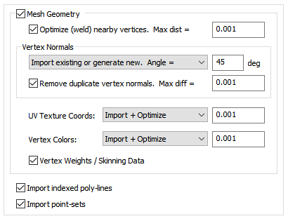
Mesh Geometry
If this checkbox is checkmarked then mesh geometry will be imported from the glTF file. Normally you would always want to keep this option enabled.Optimize (weld) nearby vertices. Max distance = #
This function will delete all redundant vertices from the polygonal mesh geometry which are within a specified distance of each other. The default distance is shown on the dialog box. This option is enabled by default so that the imported glTF mesh geometry is more refined and “welded” together. Most destination 3D programs will expect the mesh geometry to be in this refined, welded format.Vertex Normals
Vertex normals are used to specify where an object is to appear smooth and where it is to appear faceted (rough).Combo Box:
This combo box determines what is to happen to the vertex normals during the import process:Do Not Import
No vertex normals are imported. The resulting polygonal meshes will appear “faceted” in the destination 3D program.Import Existing Values
The vertex normals from the glTF file will be imported as-is.Generate New Values. Smoothing angle = #
Brand new vertex normals will be automatically generated based on a “smoothing angle”. The vertex normals from the glTF mesh data will be ignored. Normally you would not want to use this method unless you do not like the vertex normals on the glTF mesh data and wish to override them with automatically computed values.The vertex normals are computed based on the angle between abutting polygons. If the angle between the geometric surface normals of abutting polygons is less than the 'Smothing Angle' type-in value (in degrees) then newly computed vertex normals will be assigned to the polygons (they will be smoothed). Higher values make the object appear to be smoother and have less sharp corners (such as 40 to 60 degrees).
Import Existing or Generate New. Smoothing Angle = #
This is the default. If explicit vertex normals are found on the glTF mesh data then they are imported directly. If none exist then new vertex normals will be computed as per the method in the previous paragraph.Remove Duplicate Vertex Normals. Max diff = #
This is the same as the 'Optimize (weld) nearby vertices' function except that it combines redundant normals that are within a certain threshold of each other. It can make for more optimized imported meshes and possibly smaller files.UV Texture Coordinates:
UV texture coordinates are a vital aspect of 2D bitmap image texture mapping. They are 2D values associated with a glTF polygonal mesh object which defines how a planar bitmap image is to be draped over top of the mesh. This combo box determines what will be done to those texture coordinates during the glTF import process.Do Not Import
No vertex texture coordinates are imported. The resulting polygonal meshes will not be texture mapped as a result.Imported (Unoptimized)
The original glTF vertex texture coordinates will be imported as-is.Import + Optimize, Tolerance = #
The original glTF vertex texture coordinates will be imported as-is but also any redundant coordinates will be deleted based on the threshold value shown on the dialog box (any texture coordinates within a threshold of that value from each other will be welded into a single coordinate value, thus making the imported data more optimized and possibly smaller in size).Vertex Colors:
Vertex colors were somewhat more common in 3D file formats (like OpenFlight) back in the 1980s and 1990s before realtime 3D texture mapping became more prevalent. They allow explicit RGB colors to be associated with each mesh vertex. This combo box determines what will be done to those vertex colors during the glTF import process.Do Not Import
No vertex colors are imported.Imported (Unoptimized)
The original glTF vertex colors will be imported as-is.Import + Optimize, Tolerance = #
The original glTF vertex colors will be imported as-is but also any redundant colors will be deleted based on the threshold value shown on the dialog box (any vertex colors within a threshold of that value from each other will be welded into a single RGB color value, thus making the imported data more optimized and possibly smaller in size).Vertex Weights / Skinning Data
If this checkbox is checkmarked then skinning weights will be imported along with each vertex coordinate. Skinning weights are a fundamental aspect of doing “mesh deformations” via skeletons and bones. Each “skin weight” value determines how much a specific bone will influence one mesh vertex.Import Indexed Polylines
If this checkbox is checkmarked then 3D polyline geometry will be imported from the glTF file.Import Point-Sets
If this checkbox is checkmarked then 3D point-sets will be imported from the glTF file.
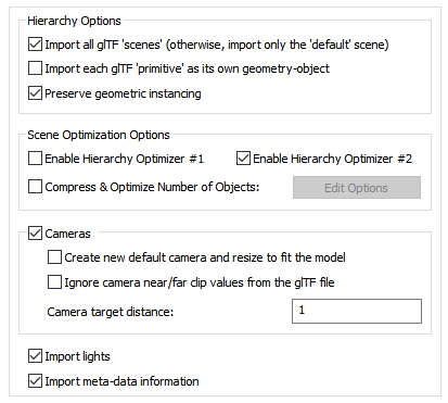
Hierarchy Options
Import all glTF ‘Scenes’ (Otherwise, Import only the ‘Default’ Scene)
Typically a glTF file contains only a single scene. Additional ‘scenes’ are mostly defined by the 3D application program which created the glTF file.If this checkbox is checkmarked then all scenes defined within the glTF file will be imported otherwise just the single ‘Default’ scene.
Import each glTF ‘Primitive’ as its own Geometry-Object
A “mesh” object within a glTF file can contain 1 or more ‘Primitives’ (each of which are smaller parts or building blocks of a larger object). A primitive summarizes all of the information about how the respective part of the object will be rendered. Basically each primitive corresponds to one WebGL or OpenGL “draw call” and with one assigned material.If this checkbox is checkmarked then each glTF ‘primitive’ will be imported as its own unique Okino instance/object definition. Otherwise all of the primitives will be compressed into a single imported object definition for better playback performance and throughput.
Preserve Geometric Instancing
If this checkbox is checkmarked then the mechanism of "instancing" will be used to try and keep the size of the imported glTF file as small as possible. For example, if the source file has 1000 bolts all derived from the same mesh primitive data, and the 1000 items have been placed in the glTF file via "instancing" then only a single copy of the geometry mesh data will be imported, but with 1000 virtual copies made of it. These virtual copy instances merely act as indexes to the original mesh primitive data instead of being full copies, which can significantly reduce the size of the final output.If this checkbox is disabled then unique and explicit copies of mesh data will be imported from the glTF file regardless of whether each copy is exactly the same as previous copies already imported.
Scene Optimization Options
Enable Hierarchy Optimizer # 1, Enable Hierarchy Optimizer # 2
These options provide methods to remove redundant hierarchy nodes (“NULLs”, or grouping folders) from the imported file. Optimizer #1 removes runs of empty folders, as well as folders with no children. Optimizer #2 is simpler, deleting empty folders which only have 1 geometry object in them. These options can also be enabled via the “Optimize hierarchy after completion” checkbox found on the options dialog box of the “Compress & optimize number of objects” option (see below).Compress & Optimize Number of Objects
This checkbox enables one of the most important and critical scene processing functions in all of Okino software. It is an integral and core part of any Okino CAD converter, and it has been added to the glTF importer for added benefits.The primary purpose of this function is to walk the imported geometry hierarchy and compress together all objects that are parented under a single folder into a one new object. For example, if you have a scene with 200 parts that are grouped under one assembly node then enabling this option will cause all such occurrences to collapse the children geometry of each imported assembly node into one object definition.
The documentation for this option can be viewed by pressing the "Options…" button and then the "Help" button on the optimizer's dialog box.
Import Cameras
If this checkbox is checkmarked then perspective and orthographic cameras will be read in from the glTF file.Create New Default Camera and Resize to Fit the Model
If this checkbox is enabled then a brand new Okino-specific 3D perspective camera will be created and made the "default" camera. The camera will be arbitrarily zoomed out to view the entire imported glTF model. This new camera will not have any relation to the cameras and views contained in the source glTF file. If this option is disabled then no new 3D perspective camera will be created.Ignore Camera Near/Far Clip Values from the glTF File
glTF files, unlike many other 3D file formats, define the near and far clipping frustum values within the file for use by the downstream glTF file viewer. These values represent the closest and furthest distances from the camera that objects will be visible or rendered. Objects outside of these near/far distances will not be rendered (ie. they will be ‘clipped’ out of the scene).Sometimes the values provided in a glTF file for the near and far clipping distances are incorrect or invalid. If that is the case then you may not be able to see some or all of the imported objects and hence you can disable this option.
Camera Target Distance
This value is used when converting from a glTF “free camera” to an imported Okino “targeted camera”. In Okino terminology, this sets the distance from the camera’s look-from location to its look-at location along its line-of-sight vector.This value defaults to 1.0 but you may have to set it accordingly relative to the overall scale of the imported scene.
Import Lights
If this checkbox is checkmarked then directional, point (position) and spot lights will be read in from the glTF file. This requires the “KHR_lights_punctual” glTF file extension.Import Meta-Data Information
Enabling this option will convert and import glTF meta-data (“custom properties”) that have been associated with the “extras properties” each object. Meta-data are things like Material type, Name, Cost, etc. as well as custom user defined attributes.
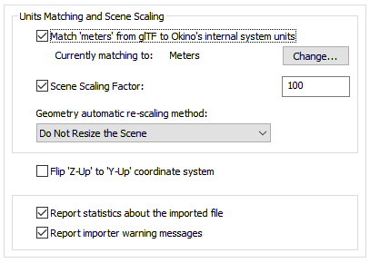
Units Matching and Scene Scaling
Match units from glTF file Okino's internal system units
These options determine what will be done when the units defined in the current glTF scene do not match those of the destination Okino “internal system units” (which is listed on the dialog box as the “Current matching to” units).If the units do not match then the importer will rescale the imported geometry based on the ratio between the glTF units and the current Okino internal system units (the “Current matching to” units).
If this checkbox is enabled then the importer will rescale all imported geometry so that the units of the glTF file will be made to match the current Okino internal system units. If the checkbox is disabled then the geometry will be imported unchanged and untouched, meaning that its scale may be "incorrect".
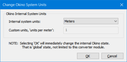
Internal System Units
This drop-down combo box specifies the current units system in effect within the internal Okino scene graph. It defaults to meters. What you need to do is select an appropriate entry from the drop-down combo box which matches the system units used by your destination program:
None No units; never do any geometry scaling Custom Custom units are in effect. See below Microinches 1e-6 inches Mils 1e-3 inches Inches 0.0254 meters Feet 12 inches Miles 63360 inches Microns 1e-6 meters Millimeters 1e-3 meters Centimeters 1e-2 meters Meters Kilometers 1e+3 meters Custom Units in "Units Per Meter"
If the drop-down "Internal System Units" combo box is set to "Custom", then this edit text control defines the "units per meter" scale factor for the custom unit system.Scene Scaling Factor = #
This option allows the imported scene to be scaled larger or smaller by a user specified amount.As examples, enter these values:
- 1.0, no scene scaling
- 1000, scale 1000 times larger
- 0.001, scale 1000 times smaller
- 4, scale 4 times larger
- 0.25, scale 4 times smaller
You can enter a value into the edit box specifying a relative scaling factor, and the model will be scaled by this factor. For example, if you enter '2.0', the model will come out twice as large.
Geometry automatic re-scaling method:
This combo box provides access to a useful mechanism which automatically rescales the imported geometry to a size best needed by other 3D software packages. This combo box can be used to automatically resize any imported model data to a useful size, such as scaled to easily fit inside a box of 2x2x2 raw working units. The various options are described as follows:Do Not Resize the Scene
No resizing is done to the imported data.Resize to 1x1x1 units
Resize to 2x2x2 units
The model data is automatically scaled up in size, or scaled down in size so that its world space extents fits inside a 1x1x1 or 2x2x2 sized unit cube.Resize to User Defined Absolute Size
The model data is automatically scaled up in size, or scaled down in size so that its world space extents fit inside a cube whose size is user defined by the type-in value shown on the dialog box. For example, if you enter the value 20 then the imported data will be resized so that its maximum extent in one or more dimensions is 20 units.Scale Larger by User Defined Factor
Scale Smaller by User Defined Factor
These options allow the imported model data to be scaled larger or scaled smaller by an absolute number. For example, if you select the ‘larger’ option and enter 10 into the type-in box, then the imported model will be scaled 10 times larger during the import process.Flip Z-Up to Y-Up Coordinate System
Okino software naturally uses a "Y" up coordinate system while glTF files may use either a Y-Up coordinate system or a Z-up coordinate system. Enabling this option will flip the source Z-up source data to the natural Y-up coordinate system of the main Okino software. If you find that the data is oriented incorrectly after import then toggle this checkbox.Report Statistics about the geometry file
If you enable this checkbox, statistics about the imported glTF file will be displayed in the console.glTF importer statistics: Polygon meshes imported: 1 15452 total triangles 14556 total vertices, 14556 total uv coords, 14556 total normals, 0 total tangents, 0 total vertex-colors 1 UV-sets (max 1 per mesh) Object definitions imported: 1 Materials (surfaces) imported: 1 5 textures imported 5 textures/images extracted Imported bounding-box has dimensions [189, 180.2, 200] Import took a total of 5.4secReport Importer Warning Messages
This will print all warning messages to the importer's console. A warning does not necessarily mean that any degradation of data has occurred or that an error has occurred.Note that deselecting this option will only cause warnings to be suppressed, not statistics or errors. If there is an error that would cause the importer to abort, then this is printed to the console when the process is aborted regardless of whether or not the "Print Warning Messages" option has been checkmarked.
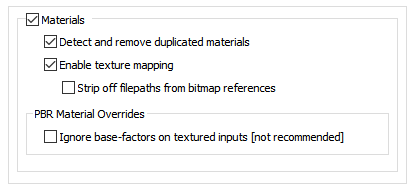
This glTF importer provides solid and robust support for “metallic-roughness” and “specular-glossiness” PBR shading models as well as their plethora of related texture channels.
In addition, the following glTF material extensions are supported:
- KHR_materials_pbrSpecularGlossiness
- KHR_materials_specular
- KHR_materials_clearcoat
- KHR_materials_transmission
- KHR_materials_sheen
- KHR_materials_unlit
- KHR_texture_transform
Enable Materials
If this checkbox is checkmarked then PBR materials will be imported from the glTF file.Detect and remove duplicated materials
If this checkbox is checkmarked then materials which are not associated with any geometry objects and which are deemed to be duplicates of each other will not be imported from the glTF file.If this checkbox is uncheckmarked then every material of the scene will be imported from the glTF file, regardless of whether they are used or not by any geometry objects.
Enable texture mapping
If this checkbox is checkmarked then 2D texture image maps that have been assigned to any of the PBR materials will be imported from the glTF file as an Okino texture definition.Strip off filepaths from bitmap references
Texture image maps are often associated with a directory file path and filename to define their location on disk such as “c:\my texture maps\brick.jpeg”. By Okino’s rules of data translation, it is better to not include the file path along with the texture image name. If this checkbox is checkmarked then the “c:\my texture maps” prefix will be stripped off the bitmap reference.PBR Material Overrides
Ignore Base-Factors on Textured Inputs (not recommended)
PBR materials have “numeric factors” associated with many of its shading parameters such as “Metallic factor”, “Roughness factor”, “Base color factor”, “Emissive factor”, “Diffuse factor”, “Specular factor”, “Sheen roughness factor”, etc.For shading parameters/channels which have a texture bitmap assigned to them, this “factor multiplier” will be assigned to the Okino texture definition if this option is set as disabled. It will modulate the texture’s intensity as a multiplier value.
If this option is enabled then the multiplier assigned to each texture definition will be set to 1.0 and hence will not affect the intensity of that texture map.
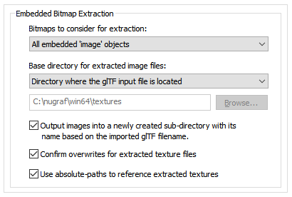
Bitmaps to Consider for Extraction
glTF files allow for embedded texture map bitmap images. This combo box provides control over which of those embedded images will be extracted to disk based files.All Embedded ‘Image’ Objects
This option will extract all bitmap images from the file to disk based files.Only 'Image' Objects Used by 'Texture' Objects
This option will extract all bitmap images from all possible glTF “texture objects” even if some of them are not actually referenced or used within the scene.Only ‘Texture’ Objects Used by ‘Material’ Objects
This option will extract all bitmap images from all glTF “texture objects” which are actually used and referenced in the scene via glTF material usage.None (Disables Embedded-Image Extraction)
No bitmap images will be extracted from the glTF file.Base Directory for Extracted Image Files
This combo box determines where the extracted bitmap images will be saved to disk.Directory From Which this Program was Executed
The extracted bitmap images will be saved in the directory where this program began execution (which is usually the same as where this program is located on disk). This is not a preferable option since that directory would normally be read-only.Directory Where the glTF Input File is Located
The extracted bitmaps images will be saved in the same directory where the glTF input file was read from. This is the default.Directory Specified Below
The extracted bitmap images will be saved in the directory indicated by the static edit box. If no directory is shown, or you want to change the current directory, then the Browse button can be pressed to select the desired destination directory.Output Images into a Newly Created Sub-directory with its Name Based on the Imported glTF Filename
As the text explains, this option will place all of the extracted bitmap images in their own new directory whose name will match that of the glTF file. This is enabled by default.Confirm Overwrites for Extracted Texture Files
If this option is enabled then you will be prompted whether an existing image file on disk should be overwritten during the bitmap image extraction process.Use Absolute-Paths to Reference Extracted Textures
If this option is enabled then the imported scene will use absolute texture path filenames such as:C:\textures\my textures\stone.pngIf disabled then the absolute texture path will be stripped from the bitmap filename.
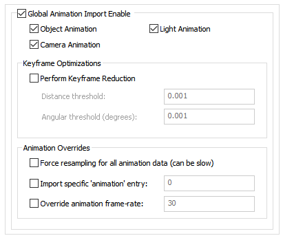
Over a period of 3 decades Okino came to pioneer, define and write the rule book on the cross conversion of animation data between all of the main industry 3D file formats and programs. This conversion process is based on our proprietary “Arctic” animation processing toolkit. The toolkit is a “one stop shop” for the handling, cleansing, correcting, processing, re-sampling and cross converting of all variations and types of 3D animation data. The glTF importer sits on top of the Artic toolkit which ensures the accurate import and playback of glTF animated entities. Ditto for the animation support in our glTF exporter.
Object Animation
If checkmarked, object animation is imported from the glTF file.Camera Animation
If checkmarked, camera animation is imported from the glTF file.Light Animation
If checkmarked, light animation is imported from the glTF file.Keyframe Optimizations
Perform Keyframe Reduction
If this option is enabled then an algorithm will be applied to the new imported keyframe lists to reduce the number of redundant keys. The type-in values determine the threshold criteria for keeping or removing a key from a list.If this option is disabled then no keyframe reduction will be done. If you want very accurate animation import then do not enable this option, or else keep the threshold values at minimum values to keep the degree of reduction low.
Distance Threshold
This numeric value indirectly controls how many redundant keyframes are to be removed from the re-sampled keyframe list. Higher values will cause more keyframes to be removed. This value is the maximum ‘distance’ the new keyframe list is allowed to deviate from the original re-sampled keyframe list. Take for example a sphere that is animated along a path; if this threshold value is set to 0.5 distance units then redundant keyframes of the animated path will be removed until such point that the sphere begins to deviate by more than 0.5 units from its ‘ideal’ location. In other words, if the value is set to 0.5 then you are guaranteed that the new reduced keyframe list will move the sphere along the same path in space, except that the sphere is allowed to deviate by 0.5 units from its original path. Smaller numbers will make the sphere adhere closer to its original path, but at the expense of retaining more keyframes.Angular Threshold (degrees)
This is the same as the previous numeric value except that it applies to reduction of quaternion and Angle/axis rotation keyframe lists. The value is measured in degrees. For example, if set to 5.0 then redundant keyframes will be removed from a keyframe list until such point that a rotation angle begins to deviate from its ideal angle by more than 5 degrees. Small numbers (such as 1.0 and 0.5) will cause less deviation and more precise rotation conversions, but at the added expense of retaining more keyframes.Animation Overrides
Force Resampling for all Animation Data (can be slow)
If this option is disabled then the raw keyframes will be imported directly.If this option is enabled then the Okino Artic toolkit will enable its “dense matrix animation” import processing pipeline. In simple terms, this will re-sample all of the imported animation data so that there will be at least one key per frame and using Bezier interpolation (plus quaternions for rotations). Since this can generate a lot of excess key frames, you may want to also enable the “Perform Keyframe Reduction” option on this panel.
Import Specific ‘Animation’ Entry = ##
As has been common with 3D gaming file formats (such as DirectX), a glTF file may have multiple “animation sets/clips” (as are known in DirectX lingo) or “animation takes” (as are known in FBX lingo) associated per object. For example, there may be animation sets/clips for “Walk”, “Jump” and “Roll over” for 3D characters.This importer will load the initial, default animation set unless this option is enabled and overridden. The animation set starts from 0.
Override Animation Frame-Rate = 30
A basic “problem”, per se, is that glTF’s animation system was implemented based on “time-specific key values” and not on “frame-rate specific key values”. glTF does not provide any means to set the “fps – frames per second” for its animation data as would otherwise be a fundamental aspect of any commercial animation program. All major animation systems written since the early 1980s are based on the latter frame-rate based system. For example, a 3D scene would be defined as being “24 frames per second” so the key values would be implicitly defined at 1/24th second intervals.As such, this importer defaults to 30 fps as the chosen frame rate for playback of the imported animation data. If you feel that this frame rate is too slow or too fast then you can override this value using this type-in edit box.

