

| You are here: Home » Import CAD Formats » NGRAIN's 3KO Solutions |
Support: 905-672-9328 Copyright © 2026 Okino Toronto, Ontario, Canada. |
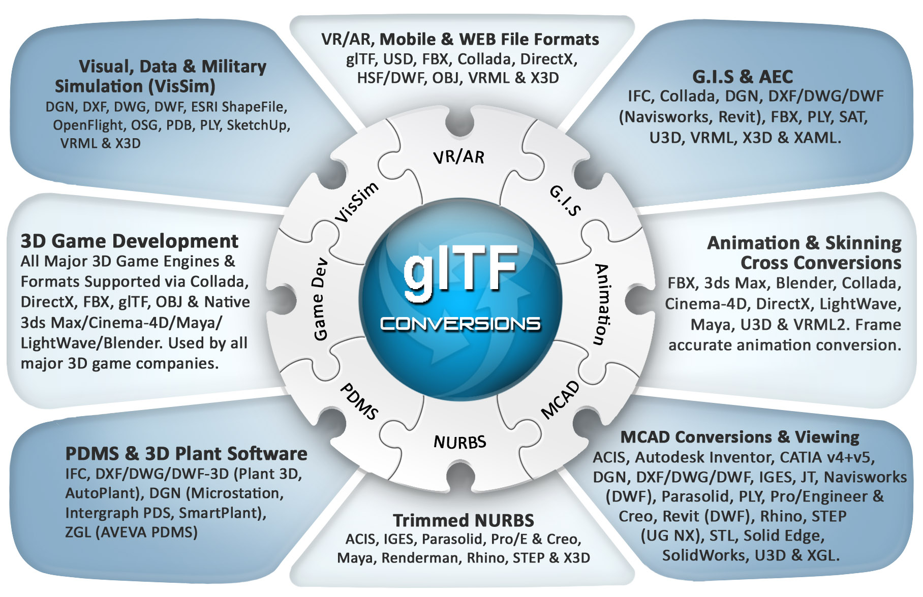
An Industry Standard, Professional CAD + DCC 3D Translation System for glTF and glB File Conversions
Okino's glTF export conversion system intelligently and robustly converts from the worlds most popular and complex 3D programs (MCAD, AEC, DCC and Animation) into highly accurate and efficient glTF (JSON) and GLB (binary) files.
The export conversion system writes out industry standard glTF and glB files with an extensive set of user definable options and processing stages to make for highly optimized files. It supports polygonal meshes with optional vertex colors, 3D point sets, NURBS surfaces and 3D spline shapes (converted to meshes or 3D line primitives), complex meta data embedding, geometry instancing, pivot point processing, Draco compression, optional lights, cameras, materials (with mutliple layers of UV coordinates and textures), automatic bitmap conversion, automatic bitmap scaling and embedding, skeleton (bones) and mesh deformation skinning, object animation, camera animation, light animation and more.
Click for larger image.
Some of our most popular file formats and programs include 3ds Max (via PolyTrans-for-3dsMax), Maya (via PolyTrans-for-Maya), Ansys STK ('Systems Tool Kit' by AGI), Autodesk Inventor, CATIA v5, CINEMA-4D, Collada, DirectX, DGN, DXF/DWG, DWF-3D (AutoCAD, Navisworks, Revit and Inventor), FACT, ESRI, FBX, HOOPS 3D, IGES, JT, LightWave, OpenFlight, Parasolid, PDB (protein database), PLY, ProE/Creo (using real PTC Creo, not reverse engineered software), Rhino, SketchUp, Solid Edge, SolidWorks, STEP (such as for Unigraphics NX & CATIA), U3D (from PDF), VRML1+2+X3D, Wavefront OBJ and others (if you don't see your required format then just email us and we'll explain the standard conversion route for that program or file format).
Please also refer to the corresponding glTF and glB import converter.
Main Selective # 1 Selective # 2
Lights Draco Compression Lines and Curves
Materials Bitmap Handling Animation
![[1]](/conv/exp_gltf_main.jpg)
![[2]](/conv/exp_gltf_selective1.jpg)
![[2]](/conv/exp_gltf_selective2.jpg)
![[3]](/conv/exp_gltf_lights.jpg)
![[4]](/conv/exp_gltf_draco.jpg)
![[5]](/conv/exp_gltf_lines.jpg)
![[6]](/conv/exp_gltf_materials.jpg)
![[6]](/conv/exp_gltf_bitmaps4.jpg)
![[7]](/conv/exp_gltf_animation.jpg)
- An intelligent 3D exporter that can reconfigure its glTF/GLB output structure in a variety of ways to provide for flexibility in repurposing any 3D scene into a properly formatted 3D document file. Accurate conversion from all sources of primary 3D data files, including MCAD, AEC, DCC and VR/AR software applications and file formats.
- Exposed user options across 9 panels to provide you with direct control over the glTF scene export process. Many options have also been added during the development process of this exporter which help smooth quirks associated with glTF files, or which help create a "nice looking 3D model" in downstream glTF viewers without having to tweak the source scene by hand.
- All main Okino 3D primitives will be converted and output as glTF meshes with vertex normals, vertex (u,v) texture coordinates, vertex colors and vertex bone deformation skinning weights.
- Support for multiple layers of uv texture coordinates for each exported geometry object. Conforming glTF viewers are only required to support two uv texture coordinate layers (TEXCOORD_0 and TEXCOORD_1), but may optionally support additional layers. By default, Okino's glTF exporter will minimize the number of uv texture coordinate layers written, to maximize compatibility with downstream glTF viewers.
- Full geometry instancing support throughout the conversion pipeline from 3D file import to glTF file export which aids in reducing the exported file size. Many 3D users are either unaware of the importance of geometry instancing or they just gloss over it when doing 3D conversions.
- Multiple methods to embed pivot points in the geometry data.
- Complete integration of Okinos 2D and 3D spline shape cross conversion engine. This is a very powerful aspect of the core Okino conversion software which allows 2D and 3D cubic spline curves, NURBS curves and spline shapes to be converted into downstream polylines or meshes. How these are output to glTF is controlled via the various drop-down combo boxes on the Curve Output Options panel.
- Excellent and robust support for glTF animated "skinned mesh" and skeleton export, which ties into the Okino Arctic toolkit. This allows PolyTrans to cross convert skinned mesh, animation and skeleton data between glTF , COLLADA, 3ds Max, Maya, Lightwave, Cinema-4D, DirectX, U3D and FBX file formats, with proper bone re-orientation, off-axis scaling removal, and so forth. Okino pioneered the animation and skeleton/bones bi-directional conversion industry.
- Exports point, spot, and directional light sources and their related parameters. Light color with embedded intensity. Note that lighting is an extension to the core glTF 2.0 specification, and may not be supported by all downstream glTF loaders.
- 18 predefined light configurations can be optionally chosen during export, which allows lights to be automatically added to the exported glTF scene if none are available in the source scene.
- Perspective or orthographic cameras. Horizontal & vertical FOV. Near and far clip plane distances, optimized for improved WebGL display..
- Mesh geometry tweaking, modification and transformations via automated operations made available by Okino's suite of polygon reduction and transformation routines. Ideal as a means to "clean up" the source meshes and apply 80-95% pre-polygon reduction to the models prior to export to glTF. The global transformation dialog box allows for these variety of transformations to be applied to the entire exported scene: Center all geometry at the origin, Make all geometry sit on the Y=0 horizontal plane, Scale geometry to be no larger than XxYxZ units, Scale, Shear, Rotate and Translate.
- Support for Draco compression, via the optional 'KHR_draco_mesh_compression' extension to glTF. When supported by the downstream glTF viewer, this can substantially reduce file sizes.
- Object, camera and light animation output with control over interpolation type (constant or linear), resampling options and algorithms to maintain Euler continuity. Okino's Arctic toolkit provides the front-end to the glTF animation export system, and thus fully utilizes its "dense matrix" keyframe resampling and reduction algorithms. Arctic also is used to ensure that all Euler animation output is properly exported (because Euler animation conversion can be fraught with problems).
- Well defined and intelligent texture map support with optional automatic embedding and resizing of JPEG and PNG bitmap images.
- Automatic texture bitmap file conversion to and from all key 2D bitmap image file formats. Images can be automatically resized to 2x2 to 8192x8192 pixels in size. Complete control is also provided over texture file path manipulation.
- Note: meta data (such as from CAD files) are not supported by the glTF specification.
The glTF format is an open 3D model and scene format designed for efficiently transmitting rich scene 3D data. It has been created and managed by The Khronos Group since 2013. glTF stands for Graphics Language Transmission Format. glTF is intended as a vendor-neutral distribution format for 3D content, bridging the gap between 3D content creation tools and applications displaying 3D graphics
glTF can best be considered a file format to be used to transmit and view 3D model data rather than for long term and high fidelity storage of 3D model data and its various attributes (such that it may be edited again in the future).
The Khronos Group describes glTF as an extensible, runtime neutral, open standard format for real-time delivery of 3D assets, which describes full scenes with compact transmission and fast load time. In other words, it is a 3D file format created to convey 3D model data into applications which require light weight and efficient models, such as for Web-based browsers, AR/VR applications and gaming applications, amongst others.
Khronos describes glTF as the "JPEG of 3D" or as a 3D content format for "the last mile." glTF minimizes both the size of 3D assets and the runtime processing needed by 3D applications. An early objective was to support applications built using the WebGL API, another open specification developed by Khronos. Based on the HTML5 Canvas element, WebGL has been implemented by most browsers as of June 2019. However, for broader applicability, glTF 2.0 is intended for use in any runtime environment or API.
glTF is a universal format for delivering 3D graphical assetsmuch like JPEG for 2D images and MPEG for videos, as noted by Tony Parisi, glTF specification co-editor. glTF 2.0 is fully graphics API and operating system-independent, opening up endless possibilities for sharing 3D between applications, across desktop, web, mobile, and virtual and augmented reality.
glTF uses a human readable JSON to describe and define the contents of the 3D transmission file. JSON is easily parsed and readable compared to other more complex 3D file formats.
For efficiency reasons, glTF 2.0 introduced the concept of a binary glTF file (GLB) which combined the JSON, binary data and 2D image files into one binary blob.
Over the last 3 decades there have been many common misconceptions held by 3D users when it comes to 3D file formats and data interchange. As we preach and explain in our daily emails, that is primarily due to misinformation put forth by Internet forums, word of mouth, print magazines, companies wishing to push their own agenda and an overall general lack of understanding about how each 3D file format works at the bit level. For example, many people coming to us believe that STL, DXF and OBJ are high-end or industry standard data interchange file formats, U3D is a universal 3D file format or that the 1980s .3ds file format is the main interchange file format of 3ds Max none of which are true or correct.
It must be understood that glTF is not a universal data exchange file format, no matter how one argues the case. It is considered to be a Last Mile file format, geared and optimized towards the last mile of data transfer into downstream viewers, WebGL, and for packing the 3D geometry + materials for efficient and direct transfers into GPUs. While not perfect in any regard, FBX, COLLADA, VRML2/X3D, U3D and Okinos .bdf can be considered semi-universal data exchange file formats, each with their own contentious history.
All 3D file formats which have come, gone, and still exist, have their rightful place in the 3D industry. There is no one size fits all 3D file format nor will there ever be. As such, one should always be careful when choosing their source and destination 3D file format used in a conversion pipeline.
Okino also likes to convey to our users about the prior history of the 3D graphics market, as few people are aware of it. One has to recall that the very peak of the 3D web streaming and interaction market was between (approximately) 1996 and 2003-2005. This was the real heyday of the 3D graphics market with hundreds of companies and products all competing for little or no market share. The peak (in our own experience) was 1999-2000 at which time the best web-based, highly compressed 3D file format was the Viewpoint VET format. In addition there was HOOPS HSF (later to be used as the core of DWF-3D), Siemens JT, VRML2/X3D, XGL (for RealityWave) and Shockwave-3D (which would morph into U3D as of 2004-2007). FBX didnt start to emerge until after 2006 (when Autodesk bought it from the Ontario Teachers Union, due to Alias bankruptcy) and COLLADA after 2007. A vacuum existed in the 3D web streaming market from the early 2000s until the late 2010s when glTF 1.0 and then 2.0 was introduced. Much can be said and argued about this new and prior history.
Okinos historical perspective, there has been many 3D Web Streaming file formats that have come and gone since the mid 1990s. There was once dozens of such excellent 3D file formats (and related supporting software programs) available from the 1995 to 2004 era, with the peak being in the 1999 to 2000 era. Such related 3D programs, their supporting companies and the file formats themselves, had mostly died out by 2005 (which was very unfortunate for the general 3D industry). Then around 2007 came about some additional then-new file formats such as COLLADA, FBX v6, 3DXML XML-3D, XAML-3D and X3D (the XML version of VRML2). However, there was not much traction for them and hence they too petered away by the late 2000s. Also, none of these then-new 3D file formats could be considered a proper, good and valid 3D Web Streaming file format as had once been available during the heydays of the late 1990s.
Given that there was a vacuum in the market for a proper and standardized 3D Web Streaming file format from the early 2000s onward, the COLLADA working group proposed an early draft of the glTF 1.0 file format at SIGGRAPH in 2012. But it wasnt until June 2017 that a revamped version of glTF 2.0 was ratified and made publicly available. Traction for this heavily revised version of the glTF file format started to gain traction in the 3D industry from 2017 onwards.
Conceptually, a glTF asset contains zero or more scenes, the set of objects to render visually. Physically, a glTF asset is a collection of related files, comprising a JSON file and supporting external data files.
In particular, a glTF asset comprises:
- A JSON-formatted file (.gltf) containing a full scene description using a node hierarchy and also descriptions and links for materials, cameras, mesh geometry, animations, and other constructs.
- Binary files (.bin) containing geometry and animation data, and other buffer-based data.
- Image files (.jpg, .png) for textures. These are the only image formats supported for textures.
- If viewing a glTF or glB file on Windows 10, please use the Microsoft 3D Viewer application and not their 3D Builder application. The latter cannot display such files properly. Blender is also another good application to view and manipulate glTF/glB files.
- glTF/glB file viewers, generally speaking, cannot handle the loading and display of very large 3D files. They were designed for light weight files for WEB viewing. If you find that such files are slow to import and display then a well implemented solution within Okino software is to run our CAD optimization system, one or two times. This is accessed via the Optimize Scene menu item located in the main menu or in the Win menu. Technically, you will want to get the Number of Instances reduced to a more sane level, as reported in the Quick Scene Statistics dialog box or the Scene Statistics Spreadsheet (Control-E keyboard shortcut).
- For the Windows 3D Viewer application and its Stats and Shading mode, the red/white striping represents those parts of the 3D model which do not have a corresponding texture map assigned.
- Some glTF file viewers may not display a corresponding bitmap texture map image if that image is not a power-of-two in both of its X and Y dimensions (ie. 2, 4, 8, 16, 32, 64, etc). A warning will be output by this glTF exporter if such a texture image is encountered before embedding it within the file. The fix is simple: set the X & Y Dimensions combo boxes to Closest on the Embedded Bitmap Conversion Panel.
This panel contains the glTF export options which are most often used or should be considered during an export process.
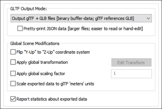
glTF Output Mode
This combo box allows you to choose which variation of a glTF and/or GLB file is to be output.Output GLB file (binary glTF) [binary buffer-data]
This produces the most efficient and smallest file size. GLB files are a binary version of the glTF format which itself is a human readable JSON encoding. Rather than have separate files written to disk, GLB files have all of the geometry, animation, texture bitmap images and shaders compressed into a single binary file. It is stated that GLB files are roughly 33% smaller than a glTF file.Output glTF file [base64-encoded buffer-data; 33% larger]
This produces a single glTF file (in JSON encoding) which is human readable. However, the data which would otherwise be referenced as external binary data (geometry, animation, skinning, bitmap images and shaders) is instead embedded within the single glTF file as base64-encoded binary data using data URIs. Such base64 encoding can increase the overall file size by approximately 33%.Output glTF + GLB files [binary buffer-data; glTF references GLB]
This mode produces two files. The primary glTF file (in JSON encoding) is human readable, and can easily be edited to make minor modifications to the scene. All binary buffer-data for the primary file is stored by-reference in a secondary GLB file, including geometry, animation, skinning, bitmap images and shaders. The secondary GLB file can technically be used on its own, but cannot be easily modified.This export mode is best used by technical end-users who may want to hand edit the JSON before loading it into their destination glTF file viewer. Example "easy edits" in this mode could include hand-changing material-assignments, hand-changing external-texture-paths, deleting part of the scene, etc.
This mode is analogous to the ".glTF + .bin" mode present in other exporters, but the '.bin' buffers are stored with the additional "structure" provided by forcing them to be fully-formed 'GLB' files, rather than being stored as a "naked" byte-buffer.
Pretty-print JSON data [larger files; easier to read or hand edit]
Normally the JSON encoded data in the glTF file is written in the most efficient and tightest manner possible. With this checkbox enabled the glTF file will be written so that the JSON encoded data will be easier to read.Global Scene Modifications
Flip "Y-Up" to "Z-Up" coordinate system
If this checkbox is enabled then a Y-Up to Z-Up coordinate system flip will be applied to the exported data. As Okino software and glTF both use a default Y-Up coordinate system this should not be necessary.By policy, all of Okinos CAD importers implicitly convert from a Z-Up coordinate system (such as from AutoCAD) into the Okino Y-Up coordinate system. As such, if you find that a 3D model appears flipped on its side in the glTF file viewer then please enable this checkbox on the glTF exporter, or, enable the equivalent Flip Y Up checkbox on the Okino CAD importer.
Apply global transformation
If this checkbox is enabled then a general purpose global transformation will be applied to each exported glTF file. This new transformation matrix will be applied to the root node in the exported glTF file.This option will allow you to, for example,
- Re-center all of the geometry so that it is centered at the origin (0,0,0) in the glTF file.
- Move all of the geometry so that it is sitting on the Y=0 (XZ) horizontal plane.
- Auto-scale the geometry so that it is no larger than a specific bounding box size.
- Scale the scene by a (X, Y, Z) value.
- Shear the scene by a (X, Y, Z) value.
- Rotate the scene by a (X, Y, Z) value.
- Translate the scene by a (X, Y, Z) value.
Since the lights and cameras are attached to this new global transformation node, they will be affected along with the geometry.
The transformation can be edited by pressing the "Edit Transform" button which will cause the following global transformation dialog box to appear:
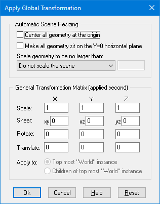
The transformation matrix will be computed in two phase: (1) the transformations specified in the top "Automatic Scene Resizing" section, then (2) the single transformation specified in the "General Transformation Matrix" section.
The values on the dialog box are described as follows:
Automatic Scene Resizing
Center all geometry at the origin
If this checkbox is enabled (checkmarked) then all the geometry data will be positioned so that it is centered about the origin. If disabled then the geometry will not be repositioned.Make all geometry sit on the Y=0 horizontal plane
If this checkbox is enabled (checkmarked) then the geometry will be repositioned so that it is sitting flush with the top of the Y plane (the horizontal plane).Scale geometry to be no larger than:
This option allows the geometry data to be automatically rescaled if it is too large. If set to 'Do not scale the geometry' then no scaling will be done. If set to '1x1x1 units' then all the objects will be scaled smaller should they exceed 1x1x1 units in total size. Likewise for the '2x2x2 units' option. If set to 'User defined maximum size' then the maximum size of all the objects can be set using the type-in numeric box. The default is '2x2x2 units'.Although not quite the same, if the option is set to Use Absolute Scaling Factor then all objects to the glTF file will be scaled absolutely by the user specified value. Thus, if you set the type-in value to 0.25 then all objects will be made 4 times smaller and if the value if set to 4 then all objects will be scaled 4 times larger. This is useful is you are converting a variety of different models to glTF format and you want them all uniformly scaled with the same scaling factor.
Transformation Matrix Values
Translate X, Y, Z
This applies a 3D translation by the specified amounts in the X, Y and Z dimensions.Scale X, Y, Z
This applies 3D scaling in the X, Y and Z dimensions. All 3 scale factors must be non-zero. Values above 1.0 will make the scene larger (2.0 will double the size of the scene) while values less than 0 will make the scene smaller (0.5 will half the size of the scene).Shear XY, XZ, YZ
This applies a linear shear in one of 3 directions:XY will shift all points in the X direction by the specified amount in proportion to the distance the points are located along the positive or negative Y axis. For example, using a value of 2.5 will shear all points by 68 degrees in the positive X direction; in other words, for every unit increase in the Y direction the X points will be shifted by 2.5 units.
XZ will shift all points in the X direction by the specified amount in proportion to the distance the points are located along the positive or negative Z axis.
YZ will shift all points in the Y direction by the specified amount in proportion to the distance the points are located along the positive or negative Z axis.
Rotate Around X Axis
Rotate Around Y Axis
Rotate Around Z AxisThis applies a rotation about the X, Y and/or Z axes. The rotation angle is restricted to the range -360 to 360 degrees. The angle of rotation is counter-clockwise when viewed from the positive to negative axis of rotation.Apply global scaling factor = #
This value allows a custom scaling to be applied to the overall exported scene. For example, if set to 10.0 then the entire exported scene (geometry, lights and cameras) will be scaled 10 times larger.
Scale exported data to glTF meters units
The glTF file format has chosen to use meters as its chosen unit of measure.Okino software is written so that all of its 3D importers and other plug-in systems recognize and respect the unit of measure associated with each source 3D file (if and where technically possible). For example, SolidWorks and Microstation files are usually in millimeters; 3ds Max and SketchUp files are usually in inches; Maya files are in cm, and so on.
If this checkbox is enabled then the exported 3D scene data will be scaled so that the source unit of measure (be it mm, cm, inches, etc) will be converted over to the chosen meters unit of measure for the glTF file.
Report statistics about exported data
If this checkbox is checkmarked then statistics will be output after the glTF file has been exported, which looks like this:glTF 2.0 Export Statistics: Number of meshes = 1 Number of polygons = 1980 Number of mesh vertices = 1723 Number of vertex normals = 1723 Number of uv texture coordinates = 1723 Number of skinned meshes = 1 Number of vertex weights = 4336 Number of perspective cameras = 1 Number of materials = 2 Number of texture maps = 1 Number of animation curves = 53 (2329 total keys) Total file size written = 225256
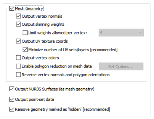
Output Mesh Geometry
This checkbox should not, in general, need to be disabled. It controls whether polygonal mesh data will be output to the glTF file. This is the main and primary geometry type used by the glTF software.A glTF 'mesh' is broken into multiple 'primitives'. Each 'primitive' basically corresponds to one WebGL draw-call and has its own material-assignment.
glTF loaders are only required to support the following mesh attributes: POSITION, NORMAL, TANGENT, TEXCOORD_0, TEXCOORD_1, COLOR_0, JOINTS_0 and WEIGHTS_0.
Output vertex normals
If this checkbox is checkmarked then vertex normals will be exported along with the mesh geometry. Vertex normals are required to provide the "smoothing" information for a mesh model.Disabling this option may make for smaller files but at the expense of making the models appear faceted.
Output skinning weights
"Mesh skinning" is the process of deforming a single skin mesh with a skeleton of bones or any hierarchical set of transform nodes. The contribution of each bone of the skeleton to the deformation of a vertex in the mesh is controlled by vertex weights. More information can be found online at this Okino WEB page:http://www.okino.com/conv/skinning.htm
If this option is enabled then a single polygonal mesh will be bound to one or more secondary objects (deformers, such as bones) via transformation matrices and weight values in the glTF file.
Only skinned meshes are supported for export, not skinned NURBS surfaces or skinned curves.
Typical sources of skinned mesh data (and which are supported by Okino software) are 3ds Max, Maya, LightWave, Cinema-4D, Softimage (XSI), COLLADA, DirectX and U3D.
Limit weights allowed per vertex: 4, 8, 12, 16
It has been our multi-decade experience that not all downstream 3D applications can handle a large number of weights per vertex. For example, the DirectX API usually only handles 4 weights. This combo box allows you to control the maximum number of weights output per vertex. The largest in magnitude weights will be chosen by the exporter.Note: Many downstream glTF viewers support an arbitrary number of weights per vertex. However, the core glTF 2.0 specification only requires support of 4 vertex weights per vertex.
Output vertex UV texture coordinates
If this checkbox is checkmarked then (u,v) vertex texture coordinates will be exported along with the mesh geometry. These are needed to define the mapping of 2D texture images onto the 3D mesh geometry. Disabling this option may result in smaller glTF files, but at the expense of not being able to map 2D texture images onto the mesh geometry.Note: no uv texture coordinates are output for 3D point set data as that can cause some downstream glTF viewers (including the popular 'BabylonJS') to fail to properly display the file.
Minimize number of UV sets/layers [recommended]
Materials make reference to the UV sets associated with geometry items. Normally only those UV sets are output to the glTF file which are referenced by 1 or more materials.If this checkbox is enabled (checkmarked) then the exporter will minimize the number of UV sets to either 0 or 1 (depending on whether there is an assigned diffuse texture map on the associated material). Since glTF is a last mile file format and not a universal 3D interchange format, there is no need to output more UV sets that are just not needed. Thus, this option was created to ensure that the smallest glTF file was made a file can be made smaller by limiting the exported UV sets to only those that are needed to render the scene properly in the downstream glTF file viewer.
If this checkbox is disabled then all UV sets associated with the mesh will be output to the glTF file. In some cases this may make the exported file larger than when this option is enabled.
Note: Conforming glTF viewers are only required to support two uv texture coordinate layers (TEXCOORD_0 and TEXCOORD_1), but may optionally support additional layers. By default, Okino's glTF exporter will minimize the number of uv texture coordinate layers written, to maximize compatibility with downstream glTF viewers.
Output vertex colours
If this option is enabled (checkmarked) then any vertex colors that are assigned to polygon vertices will be exported. The concept of vertex colors is something from the 1980s and 1990s and is rarely found in most 3D file formats or graphics packages. However, Okino software has full and complete support for vertex colors if and when such data is available during a conversion process, such as from OpenFlight, 3ds Max or Maya into exported glTF files.Enable "Polygon Reduction" on mesh data
If this checkbox is enabled (check-marked) then the glTF exporter will apply the global polygon reduction algorithm to each mesh object just prior to them being embedded in the glTF file.The algorithm allows the number of polygons in the scene to be greatly reduced. The parameters used to reduce the polygons can be modified by pressing the "Edit Polygon Reduction Global Options" button. Press the "Help" button on its corresponding dialog box to learn more about the polygon reduction system.
Reverse (flip) vertex normals and polygon orientations
If this option is enabled (checkmarked) then the orientation of all polygons will be reversed, indirectly causing the vertex normals to also face in the opposite direction. For example, if the vertex normals of the object currently all face inward then this function will cause all of the vertex normals to face outward, and cause the orientation of each polygon to flip between clockwise and counter-clockwise.Output NURBS Surfaces (as polygonalized mesh geometry)
This combo box determines whether trimmed NURBS geometry within the Okino database will be exported to glTF as tessellated mesh data.Output Point-Set data
If this checkbox is checkmarked then 3D point set geometry will be output. 'Points' are 1 or more 3D points in space, with no area or line length.Remove geometry marked as hidden (recommended)
Okino mesh geometry objects have a hidden state associated with them. It is fairly common to import a CAD file which has objects marked as being hidden.glTF does not have a "hidden" flag.
If this option is enabled (checkmarked) then such hidden geometry will not be exported, thus leading to smaller glTF files.
However, there may be cases whereby you need the entire source 3D scene to be exported, hidden and all. In such cases, this checkbox should be disabled. This will cause all geometry which is normally hidden within the Okino scene graph to be fully visible within the glTF scene.
This panel controls the output of entities to the glTF file.
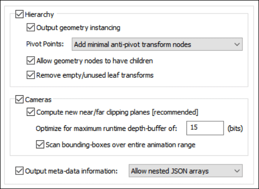
Output Hierarchy
If this option is enabled (checkmarked) then the hierarchical relationship of objects in the scene will be exported using nested glTF nodes. If this option is disabled then no hierarchy will be output and all mesh objects will be exported in flattened world-space coordinates.Output geometry instancing (use instancing to reduce file size)
If this checkbox is checkmarked then the mechanism of "instancing" will be used to try and keep the size of the glTF file as small as possible. For example, if the source scene has 1000 bolts all derived from the same mesh primitive data, and the 1000 items have been placed in the Okino scene graph via "instancing", then during export to glTF only a single copy of the geometry mesh data will be exported to glTF, but with 1000 virtual copies made of it. These virtual copy instances merely act as indexes to the original mesh primitive data instead of being full copies, which can significantly reduce the size of the final output.Note: glTF does have one key setback with its concept of instancing it does not allow for multiple instances of a common base geometry item to have different materials assigned.
If this checkbox is disabled then unique and explicit copies of mesh data will be output to the glTF file regardless of whether each copy is exactly the same as previous copies already exported.
- In a normal (non-glTF) instancing system that supports material overrides on its instances, it would be possible to define one base geometry item of a "bolt", and then define 500 "red" instances of that bolt and 500 "blue" instances of that bolt, using the same base geometry.
- However, in a glTF-style system, there would need to be 2 duplicated copies of the base geometry (one explicitly assigned a "red" material, and one explicitly assigned a "blue" material),
Pivot Points
Pivot points are a fundamental component of an animation system. In the realm of the Okino animation system pivot points define a local 3D coordinate system in the space of an object about which the scale, rotation and translation animation function curves will be applied. The pivot point in Okinos scene graph is defined by a 3D point in space and a local coordinate system defined by 3 orthogonal XYZ axes; the pivot point is itself defined relative to the local coordinate system of the underlying mesh or geometry data.For example, the virtual pivot point and its orientation axes allow a robot arm to properly rotate around its elbow joint instead of some other awkward point of the object. Any such animation placed on the robot arm will then naturally occur relative to this elbow joint.
A basic problem is that not all destination animation programs have the same concept of pivot points as with a source animation program. Some programs are more complex, some much simpler. The following options control how Okino software performs this mapping.
First, some rules need to be defined for the following explanations. Pivot point processing only needs to be done under these circumstances for the two Minimal modes:
1) The pivot point 4x4 matrix has a non-zero origin or non-aligned orientation axis. In other words, it has something interesting in it, or
2) The instance has animated channels associated with it, or
3) The (static) transformation matrix associated with an instance has off-axis scaling within it. Off-axis scaling is where rotation comes before scaling, which is basically an illegal or poorly supported situation for most 3D programs.For a grouping folder (an Okino empty instance), which is deemed to have a valid pivot point matrix, a new child anti-pivot node is added to the exported hierarchy tree - the child node is assigned the inverse pivot matrix and the original parent transform node gets the animation data. This properly applies the anti-pivot effect to the subsequent children in the tree.
The following options specify how the Okino pivot point information is exported for instance-geometry nodes:
Embed minimal pivots in geometry data
Logic same as the next option below except that the processing mode will only be invoked when one of the 3 rules explained above are valid. This leads to a cleaner conversion.Embed pivots in *all* geometry data
Logic regardless of the 3 rules explained above, this processing mode will be invoked on ALL instance-geometry nodes if any of them have a non-identity pivot matrix.The inverse pivot matrix is multiplied into the raw mesh geometry vertices. In other words, the messy pivot point problem is made to disappear by having its 4x4 matrix physically multiplied into the mesh geometry vertices.
Add minimal anti-pivot transform nodes
Logic same as above except that the processing mode will only be invoked when one of the 3 rules explained above are valid.This is the default option since (1) it results in the fewest changes to the output hierarchy tree and (2) it does not physically affect the mesh geometry coordinate data.
Output all anti-pivot transform nodes
Logic regardless of the 3 rules explained above, this processing mode will be invoked on ALL instance-geometry nodes if any of them have a non-identity pivot matrix.A new "anti-pivot" dummy node is introduced into the exported hierarchy tree, between the mesh geometry object and the parent transform node (which has the animation on it). The inverse of the Okino pivot point matrix is assigned to the transformation matrix of this new anti-pivot dummy node. This new anti-pivot node acts to pivot-in the geometry vertices prior to the animation data being applied to the geometry.
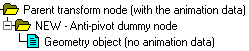
Thus, this mode splices in the pivot point matrix into the destination hierarchy tree as a new transformation node rather than to multiply the pivot point matrix into the raw mesh geometry, as with the other modes.
Ignore all pivot point data (can cause problems)
This option prevents pivot point information from being output to the glTF file. Normally you would never want to enable this option.Allow geometry nodes to have children
This option allows a form of hierarchy compression of scene nodes or visual cleanup of a hierarchy. It is disabled by default.In simple terms, if an Okino Yellow grouping folder contains a single mesh geometry object then these two nodes will be compressed together and output to the glTF file as a single node. Otherwise, the two nodes will be output separately.
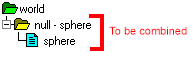
For this to occur, some conditions need to apply:
- The parent node needs to be a grouping folder (empty instance in Okino lingo).
- The parent node cannot be a skeleton joint.
- The parent and child nodes cannot have different materials assigned to them.
- The bind pose matrix for skinning needs to be the same on both nodes.
- The names of the parent and child geometry nodes must be similar, as explained further below.
- The child geometry node cannot have mesh skinning weights.
Also, the parent node needs to be named in a specific manner to that of the child geometry node. If we were to assume that the child geometry node was named example then the parent grouping node needs to be named in one of the following ways:
null - example example - mesh example - splineshape exampleShapeThe logic behind some of these rules follow from how 3ds Max and Maya name their parent transform & child geometry nodes. That carries over to this hierarchy optimizer in the glTF exporter.
Remove empty/unused leaf transforms (empty grouping nodes)
If an exported NULL/grouping node has no children, is not a joint of a bone hierarchy and has no animation on it, then such useless grouping/NULL nodes are deleted during the export process if this checkbox is enabled..If this option is disabled then such useless grouping/NULL nodes are retained during the export process into glTF and not deleted. You will want to disable this checkbox if you are exporting a file of NULL nodes and you wish all of them to be exported without pruning.
Output Cameras
If this checkbox is checkmarked then all perspective and orthographic cameras will be output to the glTF file as free (non-targeted) cameras. Adjusted near and far clipping plane values will also be output.Compute new near/far clipping planes (recommended)
The glTF format is close-to-the-metal as far as OpenGL/WebGL is concerned. What this means is that the near/far clipping planes, as specified on the camera-node, are more or less dumped straight into the WebGL perspective-projection math.If this checkbox is checkmarked then accurate near and far clipping plane values will be computed based on the bounding box of the scene.
If the scene is animated then the clipping planes will be adjusted over the entire length of the animation range if the Scan bounding-boxes over entire animation range checkbox option is enabled.
Optimize for maximum runtime depth-buffer of [15] bits
This type-in number lets you specify or guess at the number of bits for the Z depth buffer of the destination program. This number is rather arbitrary and it is up to yourself to determine a prime value. This number is being exposed just in case it may be important to your downstream glTF file viewer or application.For example, a value of 15 has often worked well for generic WebGL based applications and when well behaved 3D model data is exported from Okino software to glTF.
If you find that the displayed model has visiable z-fighting issues (ie. 3D surfaces disappear/reappear as the model is rotated) then try reducing this number lower than 15.
On the other hand, if you are taking the glTF file into a non-WebGL application, such as Unity or Unreal, and you know the depth of its Z depth buffer then you could enter a larger number in this edit box.
Output Meta-data Information
Most CAD file formats, and programs like 3ds Max and Maya, allow "meta data" to be associated with each node of a 3D scene. Enabling this option will output such meta data information to the glTF file.This option is turned off by default, as meta-data can increase file-size, and most glTF loaders/viewers will either not care for this data nor know what to do with it.
Node-level meta-data output is supported to these glTF node types: transform nodes, geometry-instance nodes, camera-nodes, and light-nodes.
Scene-level meta-data from the internal Okino scene graph is output to the glTF scene element, where the Blender 3D software expects it to be.
The following internal Okino scene graph meta data types are supported when exporting to glTF: strings, shorts, ints, floats, colors, vectors, double precision vectors, 4x4 matrices, 4x4 double precision matrices, time, double precision floats, 4 valued vectors, and 4-valued double precision vectors.
The Include additional material properties as meta-data checkbox is an experimental option added for one of our Okino customers to aid in their conversion of ProE/Creo CAD files over to glTF with their own custom added PBR materials (on their back-end of the conversion process_. This outputs an extras block to each material definition in the glTF file. The extras contain a raw dump of all the main Okino material/surface definition parameters, but no texture mapping related information. The 'KHR_materials_common' extension proposed by the Khronos Group did not get past the draft stage for glTF v1.0 and hence was not applicable as a solution. Okino reserves the right to remove this experimental feature and replace it with Okinos own proposed 'OKINO_materials_common' extension in the future.
"materials": { "name": "default", "extras": { "polytrans_material": { "diffuse": { "enabled": true, "color": [ 0.4, 0.4, 0.4], "coeff": 1.0 }, etc "reflect_opacity": 0.0, "edge_opacity_enabled": false, "edge_opacity": 1.0, "dominant_opacity": 1.0, "model": "phong", "phong_shininess": 32, "fresnel_enabled": true } } }The following is some example meta-data output in JSON:
"name": "Grouping Folder",
"extras": {
        "32-bit color": [
                0.1,
                0.2,
                0.30000001
        ],
        "32-bit float": 1.23000001,
        "32-bit float vector": [
                1.0,
                2.0,
                3.0
        ],
        "32-bit integer": 65535,
        "64-bit double": 1.23,
        "64-bit float vector": [
                10.0,
                20.0,
                30.0
        ],
        "Binary data": "\u0010 0@",
        "array 4 floats": [
                0.0,
                1.0,
                2.0,
                3.0
        ],
        "short integer": 32767,
        "tick-time": 12345
}
Allow nested JSON arrays
This combo box allows arrays-of-vector values to be output to the glTF file as nested JSON arrays. This option isnt well supported for sending and viewing such meta-data in Blender.For example, a 3-value XYZ vector element from within the Okino scene graph will get exported to glTF as a meta-data "prop" with vector "{1,2,3}:
"prop": [1, 2, 3],
However, an array-of-vectors will get exported as a set of nested-arrays in the JSON. For example, a "prop2" with an array of 2 vectors "{1,2,3}, {4,5,6}" becomes a nested-array in JSON:
"prop2": [ [1,2,3], [4,5,6] ],
Output 'flattened' JSON arrays
For the examples shown above Blenders UI does not allow showing these "nested JSON arrays". As such, this second combo box option was written. In this mode the nested arrays will be flattened during output. So, a "prop2" with an array of 2 vectors "{1,2,3}, {4,5,6}" becomes a 'flattened' array in the JSON:"prop2": [1,2,3,4,5,6],
Output meta-data as strings only
This combo box option will output all meta-data types (numbers and all) purely as string values.To follow on with the above example, this would result in output such as:
"prop": "ok_vector: (1, 2, 3)",
"prop2": "ok_vector: (1, 2, 3); (4, 5, 6)",
This panel controls the output of lights to the glTF file.
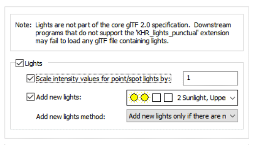
Output Lights
If this checkbox is checkmarked then all light sources of the current 3D scene will be exported to the glTF file, including those parameters for point, spot and directional light sources. Ambient light sources are not supported during export.Please note that this option is disabled by default because it requires the glTF extension 'KHR_lights_punctual' to be supported by the downstream consumer application.
Scale light intensity values for point/spot lights by #
glTF defines a PBR-based lighting model which relies on the assumption of "physically accurate" light-definitions. In particular, for this export option, it means that glTF strictly uses quadratic light drop-off attenuation (e.g. "1/distance^2" as the light's attenuation). This is incompatible with how light attenuation has been defined for decades in many other 3D software programs (which may often use linear and/or exponential light intensity drop-off vs. quadratic).This type-in value is provided as a tweaking parameter to increase or decrease the overall lighting brightness in the destination glTF viewer. Values greater than 1.0 will make the scene brighter while values below 1.0 (such as 0.5) will make the scene darker. As a suggestion, you may want to change the value by factors of 10.
This exporter will auto-adjust the lighting intensities from the source 3D file to be a good approximation to the intensity and attenuation values expected of a glTF file viewer. However, since this mapping is quite general and approximate, the final scene may appear too bright or too dark. The type-in value will allow you to make such manual adjustments.
Notes:
- Directional lights in glTF have no distance-based attenuation so they are not effected by this export option.
- As a technical suggestion, and for an ideal translation, you can modify the point and spot light definitions within Okinos stand-alone software for the following values. By doing so, the Okino ray tracer will produce lighting results which are nearly identical to that of the glTF quadratic attenuation.
- "Intensity Reference Distance" = 1
- "Decay Power" = 2
- "Near Linear Attenuation" and "Far Linear Attenuation" must be disabled
- Note: When changing the "Intensity Reference Distance" from 'D' to '1.0', you can retain the same approximate brightness by also scaling up the light-intensity from 'K' to 'K*D*D'.
Add New Lights
If this checkbox is checkmarked then new lights will be added to the glTF file. The pre-defined light locations, color and light types are chosen from the following drop-down combo box.
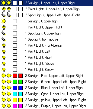
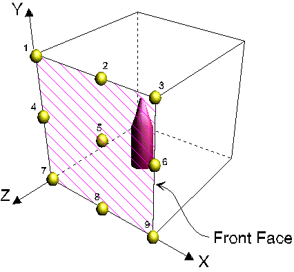
The new light sources will be placed according to the following image, along the XY plane. If you are looking down the Z axis (towards the negative Z axis) then upper-left will be (1), upper-right will be (3), lower-left will be (7) and lower-right will be (9).
- The first two icons represent the light type (Sun = directional light, Light bulb = point light, Spot light = spot).
- The second two squares represent the color of each of these two light sources.
- The text describes the location of the new light sources (see image below for visual locations).
Add New Lights Method
This combo box determines how the new lights are to be added to the exported glTF file.Merge with existing lights in the scene
This option will cause the newly chosen lights (from the drop-down combo box mentioned above) to be added to the already existing lights of the current 3D scene. In other words, all the lights of the current 3D scene will be output first, followed by the 1 or 2 new lights you have chosen from the drop-down visual list.Replace existing lights in the scene
This option will cause the newly chosen lights (from the drop-down combo box mentioned above) to be output to the glTF file, but no other light sources. None of the light sources in the original 3D scene will be output to the glTF file.Add new lights only if there are no existing lights in the scene
This option will cause the newly chosen lights (from the drop-down combo box mentioned above) to be output to the glTF file, but only if there are no existing lights in the original 3D scene. This is the default option. It will ensure that there are at least 1 or 2 new light sources added to the glTF scene if no lights exist in the original 3D scene.
This panel controls options which relate to the Draco file compression algorithm. This is used to compress the size of glTF files.
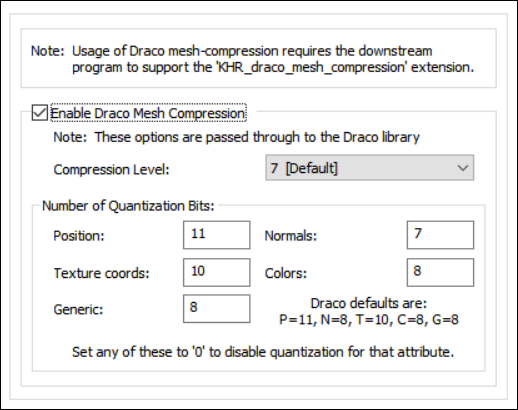
Note: Usage of Dracro mesh compression requires that the downstream glTF enabled program support the KHR_draco_mesh_compression extension.
Enable Draco Mesh Compression
Draco is a library for compressing and decompressing 3D geometric meshes and point clouds. It is intended to improve the storage and transmission of 3D graphics.Draco was designed and built for compression efficiency and speed. The code supports compressing points, connectivity information, texture coordinates, color information, normals, and any other generic attributes associated with geometry. With Draco, applications using 3D graphics can be significantly smaller without compromising visual fidelity. For users, this means apps can now be downloaded faster, 3D graphics in the browser can load quicker, and VR and AR scenes can now be transmitted with a fraction of the bandwidth and rendered quickly.
Note: These options are passed through to the Draco compression library.
Compression Level:
The compression level turns on and off different internal compression features within the Draco library.
- 10 = Slowest speed but the best compression
- 7 = The default
- 0 = Fastest speed but the worst compression
Number of Quantization Bits
These type-in boxes determine the quantization number of bits for the specified data type.In general, the more you quantize your attributes the better compression rate you will get. It is up to your project to decide how much deviation it will tolerate. In general, most projects can set quantization values of about 11 without any noticeable difference in quality.
Note: using smaller numbers will lead to smaller exported files but with worse quality.
Position:		11
Normals:		8
Texture coords:	        10
Colors:			8
Generic:		8
Setting any of these values to 0 will disable quantization for that attribute.
This panel controls the output of 3D NURBS curves and 3D spline shapes to the glTF file as poly-lines.
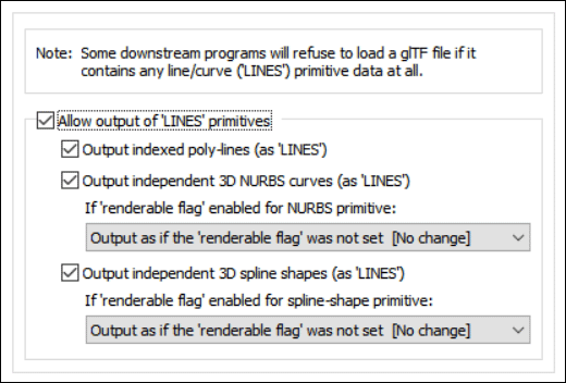
Allow output of LINES primitives
This checkbox is a convenience option that controls whether geometry will be output to glTF files are LINES entities.Note: the export of LINES is disabled by default because some downstream glTF viewers and programs will refuse to load glTF files that contain any line/curve primitive data.
Output indexed poly-lines (as LINES)
The Okino core software provided for a 3D indexed poly-line geometric primitive.If this checkbox is enabled (checkmarked) then the Okino indexed poly-line objects will be output to the glTF file as LINES entities.
Output independent 3D NURBS curves (as LINES)
The Okino core software has a very extensive NURBS curve sub-system. Each NURBS curve object can have 1 or more NURBS curves associated with it. Multiple curves inside a single object can either be considered to form a single continuous "composite" curve, or each curve can be considered unique, closed, planar (in world space) and oriented such that the curves of the object can be directly converted into a trimmed NURBS surface (in other words, the first curve forms the boundary of the surface and subsequent closed curves form the holes).The following options control how the various NURBS curve configurations can be converted during the export phase.
If 'renderable flag' is enabled in the NURBS curve primitive:
If the Okino 'renderable' flag of a NURBS curve primitive is internally enabled, and the curve(s) form closed loops, then it is possible to convert the NURBS Curve primitive into a renderable, closed 3D polygon.
The following options define what will be done to NURBS Curves primitives during the export phase when their 'renderable' flag is enabled:
Output as if the renderable flag was not set [ no change ]
The Okino NURBS curve primitive will be converted into a corresponding glTF LINES entity.Convert and output as polygon mesh
The closed NURBS curve primitive will be converted into a mesh object prior to export.Output independent 3D spline shapes (as LINES)
The Okino core software has an extensive spline primitive sub-system. This primitive accommodates one or more spline curves per primitive. If the multiple spline curves are each closed then the overall Spline Shape is termed "renderable" and can be thus converted into a polygon mesh. For example, the letter "B" can be defined by 3 Bezier curves, the first forming the outer boundary and the latter two forming holes.Note, that unlike the NURBS Curve primitive, each spline curve of the Spline Shape is composed of only a single curve segment (no composite spline curves are allowed).
The following options control how the various Spline Shape configurations can be converted during the export phase. The Spline Shape primitive also handles almost every major spline type (Bezier Spline, B-Spline, Cardinal Spline, Linear Spline, Tensioned Spline, TCB Spline), and their internal cross conversion (between spline types) or between the various spline types and a NURBS curve.
If 'renderable flag' is enabled in the spline shape primitive:
Output as if the renderable flag was not set [ No Change ]
The Spline Shape primitive will be exported as a resampled glTF LINES entity.Convert and output as polygon mesh
The Spline Shape primitive will be converted into a polygon mesh object prior to export.
Materials and texture maps are assigned to mesh objects in glTF files via material definitions. This panel controls the output of the material definitions, their associated texture maps, and provide fine grained control over the tweaking and modification of each glTF material property.
!! NOTE !! if an exported scene has its texture maps looking too bright or washed out then try one of these two suggestions:
- Enable the "Merge and mix ambient color into diffuse color" checkmark option. Then manually disable or delete the default ambient light inside of glTF.
- Or, enable the Set diffuse color of textured materials to white checkmark option. This will set up better shading parameters for glTF.
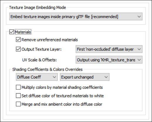
Texture Image Embedding Mode
Texture image files can either be embedded within glTF/GLB files or they can be referenced externally via URLs.Embed texture images inside the primary glTF file (recommended)
This combo box option will have the source texture bitmap image embedded within the glTF data stream.When this option is chosen then the Embedded Bitmap Conversion panel will appear.
NOTE: this is the default option because many glTF file viewers will fail to load glTF files if they cannot locate and open any externally referenced bitmap images.
Reference texture images as external/independent files
This combo box option will have the source texture bitmap image referenced externally via a RFC 1738 encoded URL path. No embedding of any bitmap image data will be done within the glTF data stream.NOTE: the bitmap file reference must be RELATIVE to where the glTF files are stored on disk and not absolute in order for many glTF viewers to open and display the file + texture images.
When this option is chosen then the Bitmap Conversion and the Bitmap Image File Paths panels will appear.
Output Materials
If this checkbox is checkmarked then materials will be exported to the glTF file.Remove unreferenced materials
If this checkbox is checkmarked then materials which are not associated with any geometry objects will not be written out to the glTF file.If this checkbox is uncheckmarked then every material of the source scene will be written out to the glTF file, regardless of whether they are used or not by any geometry objects.
Output Texture Layer
If this checkbox is checkmarked then one diffuse color texture map (that have been assigned to the material definition) will be exported to the glTF file.Please note that this glTF exporter needs to know where the source bitmap images are located or else warnings will be reported during the export process. This can be done by pressing the Modify Source Bitmap Image Search Paths button located on the Bitmap Conversion Panel panel and specifying the source of the bitmap image files.
Which Texture Layers to Output (combo box)
Okino materials allow for multiple diffuse color texture images to be layered on top of each other. However, glTF only allows for one. Hence, this combo box provides control as to which one is selected for output to the glTF file.Before explaining each of these modes, lets look at a contrived example of 3 diffuse texture maps layered on top of each other. Layers 2 and 3 are semi-transparent (due to them being alpha channeled decals) and hence can be considered non-occluders. However, layer 2 fully occludes (hides) layer 1 since brick2.jpg has no transparency in its alpha channel.
- Layer 1 -- "brick.jpg" (100% opaque)
- Layer 2 -- "brick2.jpg" (100% opaque)
- Layer 3 -- "frame.png" (decal, semi-transparent)
Last (Topmost) Diffuse Texture Layer Only
Layer 3 -- "frame.png"First (Lowest) Diffuse Texture Layer Only
Layer 1 -- "brick.jpg"First 'Non-Occluded' Diffuse Texture Layer Only
Layer 2 -- "brick2.jpg" because it 100% occludes (hides) layer 1.Last (Topmost) Diffuse Texture Layer Only
As per the explanation above, this combo box option outputs the top-most diffuse texture layer.First (Lowest) Diffuse Texture Layer Only
For the same of completeness, this outputs the first and lowest texture layer. In general you may not want to use this option.First Non-Occluded Diffuse Texture Layer Only
This is the default combo box option.It will output the lowest texture layer which was found to completely occlude (hide) all lower layers. For the example above, that is layer 2
UV scale & offsets
Each texture map reference used in an Okino material allows for the texture map to be scaled and offset in "UV space". This combo box determines how this scale and offset information is output to the glTF file.Do not output (ignore)
The information is not output. You would normally not want to use this option since the applied textures will look wrong if any of them have scaling or offsetting.Output using KHR_texture_transform extension
The texture's UV scale and offset values will be written to the file using the KHR_texture_transform extension.Embed in uv coordinates of geometry data
The texture's UV scale and offset values will be multiplied into the uv texture coordinates of each exported mesh geometry object to the glTF file.Shading Coefficient and Colors Overrides
These combo boxes provide hands-on control over how exported material shading parameters should be modified so that the exported model can be rendered nicely as it would have looked in the source 3D program. The two combo boxes and the single numeric text box provide you good control over the ambient, diffuse, specular, opacity and shininess shading coefficients exported to glTF.The first drop-down combo box selects which of these shading parameters is to be modified. Each shading coefficient has its own operation that can be selected (via the second combo box) and an optional numeric text value (via the third data entry text input box). The following describes the various shading parameters that can be controlled:
Ambient Coefficient: This controls the amount of color reflected from an object based on the ambient light in a scene. A good default value is 0.1 through to 0.3 and ideally ranges from 0.0 to 1.0.
Diffuse Coefficient: This controls the amount of color reflected from an object based on the direct light shining on it. A good default value is 0.4 and ideally ranges from 0.0 to 1.0.
Opacity: This is the inverse of transparency. 0.0 will make the object fully transparent, while at 1.0 the object will be fully opaque.
Phong Shininess: This controls the width of the specular highlight seen on an object. An ideal range is 6 (very wide) to 300 (very narrow). The default is 32.
For each material shading parameter, several actions can be performed on each material shading parameter during the import process:
Do Not Export: When this option is selected, the shading parameter is set to 0, effectively making the shading channel appear black (for color channels).
Export Unchanged: When this option is selected, the shading parameter is exported as is, with no change.
Set and Use Default: When this option is selected, the shading parameter is set to some "good" default value (as determined by the export converter). This default value will be displayed in the input text box.
Set to Specific Value: When this option is selected, the exported shading parameter will be overridden with the user specified value of the numeric input text box.
Export and Crop by: When this option is selected, the shading parameter is exported and will remain unchanged if it is less than the numeric text input value shown on the dialog box. If it is greater, then the exported value will be clamped to be no greater than the numeric type-in value. This is a good operation, for example, if you do not wish for the ambient shading coefficient to be greater than 0.3.
Export and Scale by: When this option is selected, the shading parameter is exported and multiplied by the numeric input text value shown on the dialog box
Multiply colors by material shading coefficients
Inside Okino's internal scene graph each material has a "color" and a corresponding "shading coefficient" for each ambient, diffuse and specular color definition. The "shading coefficient" can be considered a variable intensity control that brightens or darkens its corresponding color, without having to modify the color itself.If this checkbox is checkmarked then each shading coefficient is multiplied into its corresponding color value before being exported to the glTF file material. Normally you would want this option enabled as it creates a glTF material definition which is very close in appearance to an Okino material definition.
If this checkbox is not checkmarked then only the raw colors will be output to the glTF file and their corresponding shading coefficient values will be ignored. This will typically result in brighter, bolder and punchier materials, what we ourselves term "OpenGL" shading which tends to be more saturated than colors seen in photo-realistic rendering programs.
Set diffuse color of textured materials to white
This is one of those options that may come in handy for someone with particular requirements for their textured objects in the glTF file. It is patterned after a similar option from our OpenFlight export converter.If this checkbox is checkmarked then any material which has a diffuse texture map assigned to it will be output in such a way that its diffuse surface color will be set to white. Also, the textures color mixing mode will be set to Multiply
This is useful because certain real-time renderers use an "OpenGL" shading model in which the diffuse color is multiplied into the assigned texture map colors - if the diffuse material color is dark or black then the texture map will not be visible (often a problem when exporting from Maya for which the diffuse surface color is always set to black for textured materials). Enabling this option will cause the diffuse surface color to become white, and thus it will not affect the brightness of the assigned texture map.
If this checkbox is not checkmarked then the diffuse surface color will be exported unchanged.
As noted at the start of this section of help file, this option can be enabled in case texture maps look too bright or washed out within glTF (as one of two possible suggested methods).
Merge and mix ambient color into diffuse color
Enabling this checkbox will cause the materials ambient color to be mixed into the diffuse material color before the final diffuse color is exported. Disabling this checkbox will not output any ambient material color.
This dialog box controls how referenced bitmap texture files will be handled during the glTF export process, such as being automatically converted to JPEG or PNG.Notes:
- This panel only appears when the Reference texture images as external/independent files combo box option on the Materials Panel is chosen.
- Bitmap texture map images can also be embedded directly within the glTF file by enabling the alternative Embed texture images inside the primary glTF file option on the Materials Panel.
Texture Bitmap Handling Method (Combo Box)
This combo box determines the preferred method to output texture bitmap disk references:1] No Bitmap Conversion, No Bitmap Filename Changes
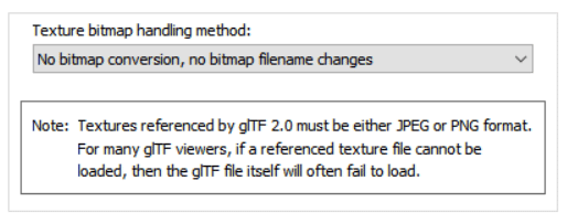
If this combo box option is selected then:
- The texture image will be placed in the glTF file as a texture reference.
- The filename and file path to the texture image on disk will not be changed.
- The filename extension on the bitmap reference will not be changed.
- The path to the bitmap will not be changed.
- No automatic bitmap conversion will be performed.
Note that texture images referenced by glTF must be in either JPEG or PNG format. For many glTF file viewers, if a referenced bitmap image file cannot be loaded then the glTF file itself will often fail to load.
2] Replace File Extension For All Bitmap References
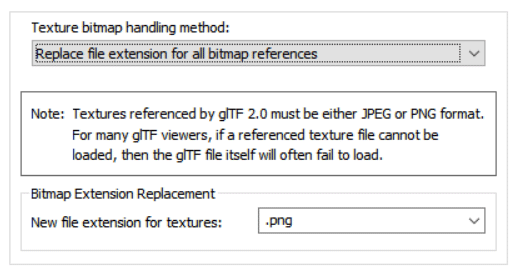
This is similar to option # 1 above, except that:
- The file reference placed in the glTF file will be changed such that its file extension is changed to that specified on the dialog box.
For example, if the option is set to PNG then all bitmap filename references will be changed so that their file extensions end in .png
Note that glTF files only allow for JPEG and PNG bitmap texture images.
This is a useful option when all of the referenced texture maps have already been converted to this desired file format on disk.
3] Auto-Convert Bitmap Files to Another Format
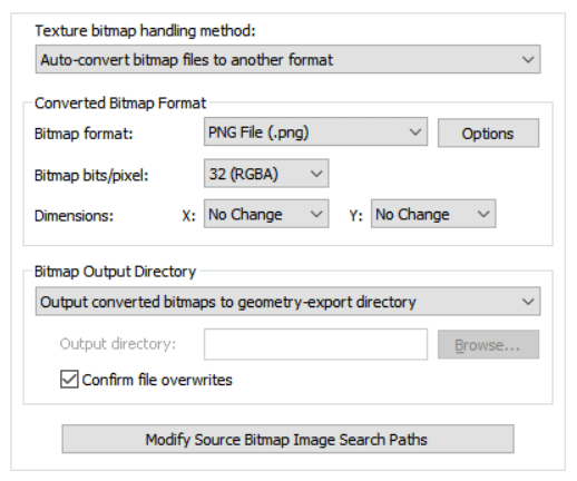
If this combo box option is chosen then all 2D bitmap images that are used by the current scene will be automatically tagged and converted into a new user-specified 2D bitmap file format on the local disk. The bitmap image will be written to the glTF file as a file reference and not as an embedded texture image.
For example, if the scene makes references to PNG bitmap files then this option can be selected so that the PNG images are automatically converted to the TIFF format.
If the bitmap texture(s) cannot be found in the location specified by the pathname pre-pended to the texture filename then the glTF exporter will search for the texture(s) in all directories specified in the file search paths (these can be modified by pressing the "Modify Source Bitmap Image Search Paths" button).
Converted Bitmap Format
Bitmap File Format (Combo Box)
This combo box lists the desired destination bitmap file format that all texture bitmap images should be converted into.
Bitmap Bits/Pixel: 2, 4, 8, 24 (Combo Box)
This combo lists determine the number of bits/pixel to write out to the new 2d bitmap file. The default is 24 bits. A color quantization algorithm will be used for the 2, 4 and 8 bits/pixel output formats. Not all bitmap file formats can accept 2-8 bits/pixel (e.g. in particular JPEG).
Dimensions: X = #, Y = #
These two drop-down list boxes determine the X and Y resolution for the converted bitmap file(s):
No Change = Do not change the X or Y size Closest = Use the next highest power-of-2 size 2, 4, 8, ... 256, 512 = Choose a specific size for the X or Y dimension Bitmap Output Directory
This combo box determines where the new bitmap file will be written to. Note that enabling the "Replace file paths in all bitmap file references" option or the "Strip file paths from all bitmap references" option from the 'Bitmap Image File Paths Panel' will change the path prefix for the converted bitmap even though it was saved to disk in the location specified by one of these options.
Output Converted Bitmaps To Geometry-Export Directory
The new bitmaps will be written to the directory where the exported files are being written to.
Output Converted Bitmaps To The Specified Directory
The new bitmaps will be written to the directory specified by the input text edit box (labeled as 'Output Directory'). This directory can be changed by pressing the 'Browse' button.
Confirm File Overwrites
If this checkbox is enabled (checkmarked) then the bitmap converter will confirm any potential overwrites of existing bitmap files on disk that have the same filename and extension as the one being written. If this option is disabled then no confirmation will be made.
Modify Source Bitmap Image Search Paths
In specific circumstances it may be necessary to inform the USD exporter where your source bitmap images are located so that automatic bitmap file conversion process or the image embedding process can locate and load the images.
If the glTF exporter reports warnings that specific images could not be located during automatic bitmap conversion or embedding, then press this button so that the Search-Paths dialog box appears. Using this dialog box you can inform the USD exporter where the source bitmaps are located.
This dialog box controls how referenced bitmap texture files will be embedded into the exported glTF data stream as either JPEG or PNG files.
NOTE: This panel only appears when the Embed texture images inside the primary glTF file combo box option on the Materials Panel is chosen.
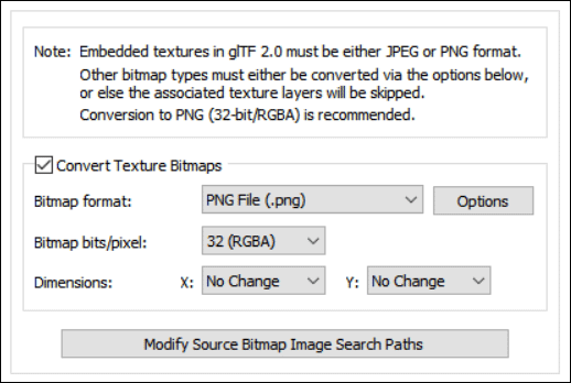
Convert Texture Bitmaps
If this checkbox is checkmarked then referenced texture maps on a material will be embedded into the exported glTF data stream as either JPEG or PNG files.The additional options on this panel allow for the bitmap file format to be chosen (JPEG or PNG), the bits per pixel (2 through 32) and the X & Y dimensions.
If the bitmap texture(s) cannot be found in the location specified by the pathname pre-pended to the texture filename then the glTF exporter will search for the texture(s) in all directories specified in the file search paths (these can be modified by pressing the "Modify Source Bitmap Image Search Paths" button).
Modify Source Bitmap Image Search Paths
In specific circumstances it may be necessary to inform the glTF exporter where your source bitmap images are located so that automatic bitmap file conversion process or the image embedding process can locate and load the images.If the glTF exporter reports warnings that specific images could not be located during automatic bitmap conversion or embedding, then press this button so that the Search-Paths dialog box appears. Using this dialog box you can inform the glTF exporter where the source bitmaps are located.
If a texture bitmap file reference is to be added to a glTF file then this panel controls what will be done to the file path of that image filename.
Note: This panel only appears when the Reference texture images as external/independent files combo box option on the Materials Panel is chosen.
Note: it is vitally important that all bitmap texture image references are provided as relative-path and not absolute-path.
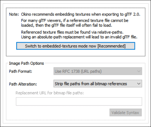
Path Format Combo Box
This combo box determines what kind of file path format will be used.Use the RFC 1738 (URL paths)
All bitmap file paths written to the glTF file will be converted into the "RFC 1738" URL format specification.Path Alteration
In most 3D graphics programs and file formats a texture map reference is defined as a relative or absolute disk-based directory path which is appended with the name of the bitmap texture map + its file extension, such as c:\files\textures\bitmap.tif. This combo box and its options allow the directory path to be stripped or replaced with something new.No replacement (no change)
If this option is chosen then the file path and texture bitmap image reference will not be changed.Strip file paths from all bitmap references
If this option is chosen then any file path on a bitmap image reference will be stripped off. For example, "C:\polytrans\bitmaps\texture.tif" will be output as "texture.tif".Replace file paths in all bitmap file references
This option allows all exported bitmap references to be prefixed with a new file path. This might be useful, for example, if all of the bitmap files are located in one specific directory or if you wish to change the prefix on the exported bitmap references.To choose the new file path press the Browse button.
If the Use the RFC 1738 Standard (URL paths) option has been chosen from the Path Format combo box, then the type-in edit box will instead contain the new RFC 1738 compliant URL and not a directory path. This user-entered URL will be used to prefix the bitmap image reference.
For example, if an original texture map references the filename:
c:\files\textures\bitmap.tifand the new URL is specified on this dialog box as:
http://www.okino.com/images/then the bitmap filename will be stored in the file as:
http://www.okino.com/images/bitmap.tif
Animation Options Panel
This panel controls the export "animation conversion engine". This engine allows object, camera and light animation data to be exported cleanly and properly to glTF.
Okino pioneered the concept of animation cross conversion and hence has a very complex & refined conversion engine which is used all throughout the 3D production market. This conversion process is based on our proprietary "Arctic" animation processing toolkit. The toolkit is a "one stop shop" for the handling, cleansing, correcting, processing, re-sampling and cross converting of all variations and types of 3D animation data. The glTF exporter sits on top of the Artic toolkit which ensures the accurate export of glTF animated entities. Ditto for the animation support in our glTF importer.
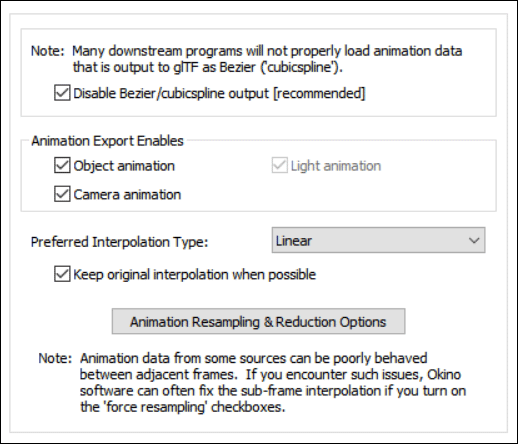
NOTE:
Animation data from some 3D file sources can exhibit poor interpolation behaviour between adjacent frames. For example, when playing back such animation data in a downstream glTF file viewer a rotating object may flip-flop in different directions in between the keyframe locations; programs like 3ds Max, Maya, LightWave and Cinema-4D will not encounter such problems because animation playback is always done at the key frame locations and not in between the frames.
The basic problem, per se, is that glTFs animation system was implemented based on time-specific key values and not on frame-rate specific key values. glTF does not provide any means to set the fps frames per second for its animation data as would otherwise be a fundamental aspect of any commercial animation program. All major animation systems written since the early 1980s are based on the latter frame-rate based system. For example, a 3D scene would be defined as being 24 frames per second so the key values would be implicitly defined at 1/24th second intervals. The problem comes about when animation data from these frame-rate-specific 3D programs is exported over to a glTF viewer; such viewers allow the playback slider to be set to any point in time and not restricted to strict frame-rate intervals (ie. playback at exactly 1/24th of a second intervals). In these source 3D animation programs (such as from 3ds Max or Maya), the animation data is mathematically undefined between key frames and thus they may appear to flip or go wild when played back in a glTF file viewer. This is where Okinos long-time-implemented keyframe resampling sub-system comes to the rescue.
If you encounter such issues then the Okino software can often fix the sub-frame interpolation problems if you turn on the Force Resampling checkboxes found on the dialog box accessed via the Animation Resampling & Reduction Options.
Disable Bezier/cubic-spline output
It goes without saying that the 3+ decade industry standard for animation playback is done with the use of Bezier curve interpolation methods. The problem is that the glTF file format and downstream glTF viewers do not implement its corresponding cubicspline interpolation method properly, if at all. For example, Blenders glTF importer ignores/drops all of the Bezier interpolation information from the glTF file and reverts to a linear interpolation method. Okino pioneered the animation conversion industry and hence understands the conversion and playback of animation data very well.Rather than force all animation data to be output in constant or linear interpolation modes (which are very Neanderthal and primitive in their nature), Okino chose to map over its animation data to the cubicspline method as best it could, given the mathematical limitations of its implementation within the glTF file format. But please do keep in mind that, from our experience, downstream glTF programs may just ignore such Bezier/cubic-spline data and revert to the simpler linear interpolation mode.
NOTE: quaternion-based animated rotations will always be output via constant or linear interpolation modes and never the cubicspline mode. This is because the glTF implementation of quaternion rotation interpolation is mathematically faulty or unexpected. This fault and our proposed fix has been submitted to the Khronos Group, via their glTF GitHub, as issue # 2008.
- The basic issue is that glTF and/or Blender has chosen to interpolate animated XYZW quaternion values as 4 independent curves (similar to how Euler-based rotations are implemented and interpolated) and not as one unified 4-vector. This is referred to as "RQBez" ("Renormalized quaternion Bezier curve") in their literature. Rather, glTF (and Blender) should have implemented the industry standard sqlerp() method as introduced by Shoemake in 1985 and used in all commercial animation programs that provide quaternion-based rotation animations. The RQBez method also exhibits a fundamental flaw when the computed value from the 4 animation channels passes too close to (0,0,0,0).
Object Animation
If this option is enabled (checkmarked) then object animation data which is currently contained within the internal database will be exported.Camera Animation
If this option is enabled (checkmarked) then camera animation data which is currently contained within the internal database will be exported.If this checkbox is grayed out (disabled) then you will first need to enable the Output Cameras checkbox on the Selective Output Options Panel # 2.
Light Animation
If this option is enabled (checkmarked) then light animation data which is currently contained within the internal database will be exported.If this checkbox is grayed out (disabled) then you will first need to enable the Output Lights checkbox on the Light Output Options Panel.
Preferred Interpolation Method: Constant, Linear, Bezier
This combo box determines which type of keyframe interpolation method should be used for the exported glTF file. The possible choices are constant, linear and Bezier. The latter (Bezier) is only available when the Disable Bezier/cubicspline output checkbox is disabled please refer to the explanation for that checkbox as to why downstream glTF-enabled programs ignore or poorly implement cubic-spline interpolation methods.Keep Original Interpolation Method When Possible
If this checkbox is enabled then the animation resampling process will attempt to preserve the interpolation method used in the original source animation data. This can often be accomplished, but not in all cases. When it can be accomplished, then the animation data sent to the glTF file will preserve the same interpolation type as the original source animation data. Otherwise, the animation output to glTF will use the "Preferred Interpolation Method" you have specified above.You will typically want to keep this checkbox enabled, unless you have specific reasons for wanting all your glTF animation controllers to use the same interpolation type.
NOTE: When this checkbox is enabled, keyframe resampling might still occur. However, the interpolation type of the resampled keyframes will have the same interpolation method as the original source animation data, when possible (or the "Preferred Interpolation Method" when the original source animation data's interpolation method cannot be used.)
If this checkbox is disabled then the resampling process will use the "Preferred Interpolation Method" you have specified above. If the original animation source data has a different interpolation type, then resampling must occur. If the original source data has the same interpolation type as the "Preferred Interpolation Method" you have specified above, then resampling will only occur if otherwise mandated.
Animation Resampling and Reduction Options
Pressing this button will show the animation resampling and reduction options dialog box. This, in general, controls the precision and reduction options used globally during animation resampling (for both import and export). If you find that your exported animation data looks jittery or does not hit target translations/rotations, then reduce the tolerance values.If you disable keyframe reduction, then resampled animation data will have a key at every frame. You might have a specific reason to desire that output. Leaving keyframe reduction enabled, but setting the tolerance values to zero, will result in a curve which perfectly fits the original curve at all frames, but has all redundant keys eliminated. For example, if a channel is actually non-animated, then leaving keyframe reduction enabled with a zero tolerance will result in far fewer keys than entirely disabling keyframe reduction.