

| You are here: Home » Import CAD Formats » AutoCAD-Revit-Navisworks (DWF-3D) |
Support: 905-672-9328 Copyright © 2026 Okino Toronto, Ontario, Canada. |
This geometry import converter reads in USD binary and ASCII files in a mathematically precise and intelligent manner. It is based on Okinos Arctic geometry and animation processing toolkit which ensures that the USD data will convert over to all supported 3D export file formats and programs in an exacting manner. It is a deep and complex importer.
Click for larger image.
Please also refer to the corresponding USD export converter.
It provides support for all key features of USD files including:
- N-sided polygon meshes with optional UV texture coordinates and vertex colors
- 3D spline shapes
- 3D NURBS curves
- Trimmed NURBS surfaces
- Hierarchy & deep hierarchy optimization
- Geometry & hierarchy instancing
- PBR materials
- PBR-centric texture mapping
- Automatic extraction of bitmap images from USDZ package files
- Skeleton (bones) and mesh deformation skinning
- Object and camera animation with optional animation keyframe re-sampling and reduction
- CAD-like units matching
Click on any one of the small screen snapshots to jump to the corresponding section of this WEB page:
Selective-1 Selective-2 Units Matching
Materials NURBS Geometry Bitmap Extraction Animation See also:
USD from the Perspective of Okino
Some Basic Fundamentals of USD
![[1]](imp_usd_selective1_sml.jpg)
![[2]](imp_usd_selective2_sml.jpg)
![[3]](imp_usd_units_sml.jpg)
![[4]](imp_usd_materials_sml.jpg)
![[5]](imp_usd_nurbs_sml.jpg)
![[6]](imp_usd_bitmaps_sml.jpg)
![[7]](imp_usd_anim_sml.jpg)
The USD format (Universal Scene Description) is an open 3D model and scene format designed for efficient storage and streaming of 3D asset data. It is a high-performance extensible framework and ecosystem for describing, composing, simulating, and collaboratively navigating and constructing 3D scenes.
- .usd General format in either ASCII or binary
- .usda ASCII, human-readable (crate format)
- .usdc - Binary format
- .usdz - Packaged format (a OPC-style ZIP file with a USD file + texture images).
Pixar Animation Studios originally created the USD platform (as its fourth generation variation after its Marionette & Preso systems) to improve studio-wide collaborative workflows. USD provides a concept of "scene composition", building a unified scene from potentially thousands of loosely-coupled source assets. For example, the mesh, rigging, materials, and animation for a single model might all come from different "layers" (files), each created and maintained by a different artist or department. Layers can store multiple "variants" of any given data, helping to solve problems of versioning/approval. The coupling between layers is very dynamic and loose, allowing for greater flexibility during the production process. The entire USD system is designed to facilitate a large studio making feature films, with all of the scale that that implies.
USD should be considered more of a code framework (OpenUSD) for use in group collaboration, to help with the aggregation of various 3D data sources into a unified scene through a process referred to as scene composition. A subset of that code framework provides for reading and writing USD disk-based files as well as rendering USD scenes (Hydra). The system is rather complex to implement (for software developers) and to use (from first principles) as a 3D graphics artist. The USD file format itself is not for faint of heart and is best read/written using the OpenUSD SDK + various programming APIs. More commonly used ASCII 3D file formats such as COLLADA, VRML2 and Wavefront OBJ are much easier to manipulate/understand/use on a human level basis.
In 2018 Apple adopted a subset of USD technology as part of their own AR/VR initiative. Most 'USDZ' files that can be found online are related to this specific subset of USD functionality. For example, an Apple-compatible USDZ file can only contain a single 'layer' file, bundled with a set of embedded textures. As a file-format, these USDZ files are used for web-based asset-delivery to an AR/VR viewer, largely ignoring the collaborative-workflow features built into USD. This is why youll see 'USDZ' files commonly used by Apple compared to the more widely used and adopted glTF or FBX by other software vendors.
The file format was made open sourced in 2016 by Pixar and supported by NVIDIA as OpenUSD - OpenUSD.org. Their Omniverse framework is built upon OpenUSD but with many of their own extensions, such as their own implementation of animation for USD.
Overall, from its 40 year history of 3D converter development and experience, Okino considers USD to be a highly complex file format and ecosystem to both implement, roll-out and support in the long term (along the lines of Okinos STEP, IFC and Microstation DGN MCAD conversion systems).
USD does have its place within the 3D industry but other formats such as glTF, COLLADA, FBX, VRML2 and Wavefront OBJ are more ubiquitous for general 3D model asset and scene sharing, whereas USD excels more at collaborative work scenarios. USD also comes with versioning concerns that many other file formats don't suffer from at all or as much. One cannot use the words better or best when it comes to the plethora of 3D file formats which exist as each can only be properly differentiated within its related usage context.
The core flexibility that makes USD so attractive can also make it difficult to use. The collaborative workflows operate more smoothly if the overall layer-structure is decided in advance, based on the team's requirements. USD is an "enterprise-grade" tool that can make life easier for large teams operating at-scale but can risk adding too much complexity for smaller teams (or individuals). The OpenUSD framework is incredibly extensible, but that also risks fragmentation of the user-base. For example, there are plugins to achieve either MaterialX or NVIDIA MDL materials but not all consumers of USD files will support those extensions.
USD organizes data into hierarchical namespaces of Prims (short for primitive). A Prim is the smallest atomic object that can be defined, customized and manipulated within USD. Prims are technically containers of Metadata, Properties, and other Prims.
In addition to child Prims, each Prim can contain Attributes and Relationships, collectively known as Properties. Whereas Prims provide the organization and indexing for a composed scene, Properties contain the real data. Attributes have typed values that can vary over time. Relationships are multi-target pointers to other objects in a hierarchy. Attributes are the workhorse of storing actual data inside a Prim and are often defined as part of Schemas to make it easier to access context-relevant data from within an instance of that Type.
Both Prims and Properties can also have (non-time-varying) Metadata. Metadata is the lightest-weight form of name, value scene description; it is light because unlike Attributes, Metadata cannot be time-varying, and because Prims and Properties can possess Metadata, but Metadata cannot itself have Metadata.
Prims and their contents are organized into a file abstraction known as a Layer. Layers are a component of the collaborative nature of USD. Each layer in USD signifies a users opinion on assets inside a stage. Layers can override other Layers. A Layer contains zero or more Prims, that in turn describe Property and Metadata values. Each layer possesses an identifier that can be used to construct references to the Layer from other Layers.
A USD Stage provides the mechanism to view all the assets in a current USD scene. The Stage is the USD abstraction for a scene graph derived from a root USD file, and all of the referenced/layered files it composes (in a hierarchical parent/child order).
You can stack USD Layers together using the subLayers composition arc, and the composition engine will resolve the data contained in such ordered (nestable) LayerStacks similarly to how layers in Photoshop are composed. This is one of the more powerful aspects of using USD, whereby the USD composition engine will resolve the resulting graph in a predictable way; a stronger Layer will override any weaker Layers.
VariantSets allow an asset creator to bundle different multiple variations of an asset all into a single package with a variant selector that downstream asset consumers can switch, non-destructively, in stronger layers to change the variation they desire; any prim can define multiple VariantSets, which can vary along dependent or independent axes.
3D file formats are often associated with a major a minor version. For example, there is glTF v1.0 and glTF v2 formats. There is VRML 1 and VRML2. There is FBX v5 (Kaydara), FBX v6 (Alias|Wavefront) and FBX v7 (Autodesk). However, that concept has not been rolled over into the USD framework, at least at the time of this writing.
Since USD follows a "large studio" model it does not seem to pay much attention to backwards-compatibility of existing files. In a large studio setting, all machines would typically have software fixed to a given version-number across the entire production. If software was updated during production, it would likely be done in a controlled roll-out, supervised by IT professionals, with attention paid to any data-changes that needed to be made for compatibility. The USD file format itself does not provide versioning information that is found in other commonly used 3D format formats. The USD SDK itself does not provide any versioning information. So, as the data-model morphs over time (such as revisions made by Pixar) there is no way to track what automatic-updates might be applicable.
One must firmly keep in that that USD is not just a 3D file format but rather a large and complex framework. That framework, for example, allows for internal and external plug-ins to be added for increased functionality, such as to handle MaterialX shader files, Wavefront OBJ files, FBX files, etc. Higher level consumers and users of that framework do not generally care where the data came from -- they simply consume the unified view provided by the USD frameworks data-model (Prims + Attributes + Properties + Meta-data).
Because the USD framework and SDK is such a "constellation of plug-ins" in the first place, it is very difficult to lock down any meaningful version-number. Hypothetically, you might be running off the same SDK version "USD XX.YY" as with your co-animator, but do you have all the same plug-ins installed? Do you have the same MaterialX plug-in installed? Did one of you drop in a third-party "asset-resolver" plug-in so that you can reference assets that live inside an "Autodesk Vault" server? Or maybe another animator's studio wrote their own file format plug-in so that they can load up the output of their custom particle-system simulation as time-varying meshes inside USD. These issues all complicate the concept of USD file and project versioning.
In theory, if one carefully tracked USD data-model changes over time, one could possibly detect the rough "era" of a given USD file. However, that would not be particularly easy to do and such information would not be overly helpful. In a best-case scenario, Okinos USD importer might be able to say "Note: your file might be 5+ years old and as such might not load properly" but there are not many cases where we could make that distinction amongst different vintages of USD source files.
Having both USDa/USDc and USDZ file formats may be confusing to many people. This section will provide a short overview to differentiate them.
The OpenUSD file format specifications home page for USDZ succinctly explains why Apple chose to develop the much simplified USDZ subset. Simply put, USD by itself is just too complex for consumer software applications, such as Apples VR/AR consumer initiative. As they state:
Part of USDs appeal is its ability to create a 3D scene by composing many modular data sources (files) together into successively larger and larger aggregations. While very useful within content creation pipelines, this aspect can be a very large hindrance to using USD to deliver assets in the form that they have been built up. In particular, even though USD does provide several means of flattening multiple USD files into a single file, there is, by design, no mechanism for representing images/textures as the scene description encodable in USD files. Content delivery is simplified and useful on a broader range of platforms when the content is:
- A single object, from marshaling and transmission perspectives
- Potentially streamable
- Usable without unpacking to a filesystem
In that manner, a USDZ package is an uncompressed zip archive that is allowed to contain the following file types:
- USD 3D file: .usda, .usdc, .usd (presently, only one such file)
- Images: PNG, JPEG or EXR
- Audio: M4A, MP3, WAV
The key intention of a USDZ package is to provide perfectly reproducible results in arbitrary consuming environments.
USD differs from similar formats such as COLLADA, FBX, glTF and Okino .bdf format based on why Pixar chose to create it and how they utilize it within their 3D production pipelines.
Key differences of USD over other similar 3D file formats:
- A single USD scene can be collaboratively changed by multiple animators at the same time and at remote locations (such as via NVIDIA Omniverse and its connectors to common third party DCC/Animation packages).
- As claimed on the OpenUSD WEB site:
- USD addresses the need to robustly and scalably interchange and augment arbitrary 3D scenes that may be composed from many elemental assets.
- USD provides for interchange of elemental assets (e.g. models) or animations. But unlike other interchange packages, USD also enables assembly and organization of any number of assets into virtual sets, scenes, shots, and worlds, transmitting them from application to application, and non-destructively editing them (as overrides), with a single, consistent API, in a single scenegraph. USD provides a rich toolset for reading, writing, editing, and rapidly previewing 3D geometry, shading, lighting, physics, and a growing number of other graphics-related domains. In addition, because USDs core scenegraph and composition engine are agnostic of any particular domain, USD can be extended in a maintainable way to encode and compose data in other domains.
- Like many other interchange packages, USD provides a low-level data model that stipulates, at a file format level, how data is encoded and organized, plus a (extensible) set of high-level schemas that provide meaningful APIs and organization for concepts like a mesh or a transform. With such a foundation one can create asset definitions with geometric, material, lighting, and other properties. But USD goes further to provide a freely combinable set of Composition Arcs that can be used to package, aggregate, vary, and override primitive elements and assets, with a high-performance runtime evaluation engine, embodied in a compact scenegraph known as a Stage, for resolving the resulting composed scene description and extracting (and authoring) data from it.
- USDs most basic composition arc, the subLayers operator, facilitates multiple artists in different departments, or within the same department, to simultaneously work on the same asset or scene, by allowing each artist to work in their own file (called a Layer), all of which will be combined and resolved in a strength ordering clearly specified in the USD files themselves. This ability is not a magic bullet that can automatically adjust shading data in a stronger layer when the modeling artist changes the topology of geometry defined in a weaker layer, but it allows each artist to work independently without erasing or editing any other artists work, and helps to provide a clear audit trail of changes that aids in addressing problems like the changing-topology problem.
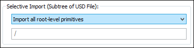
Selective Import (Subtree of USD File)
These options determine which portion of the USD file is to be imported. That is determined by the path to a specific sub-Prim in the file.
USD Stages are organized in a hierarchy of Prims. There is a special root prim at / and it may have N-number of direct Prim descendants, each of which can have their own tree of Prim descendants.
The path to a Prim is described by a string which starts with the root prim / and contains the Prim name separated by the path separator / until the last component is the desired Prims name.
For example /Car/Wheel/Tire refers to the Tire prim which has parent Wheel and grandparent Car. Cars parent is the special root prim /.
For example, /Root/Child/Grandchild represents an absolute prim path of three nested prims in this contrived .usda file:
#usda 1.0
def "Root" {
    def "Child" {
        def "GrandChild" (
            add variantSets = [ "modelingVariant" ] {
                def "GreatGrandchild"   {}
            }
        }
    }
}
Import all Root-Level Primitives
This option imports the entire file.Import Sub-Tree Below the USD defaultPrim
USD files can have a defaultPrim metadata defined on a Stage. It must be a top-level Prim on the stage. If it is defined, and this option is chosen, then the portion of the USD sub-file specified by the defaultPrim will be imported.Import Sub-Tree Specified by the Following SdfPath
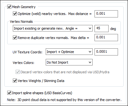
This option imports a sub-portion of the file as defined by the Prim path such as /Car/Wheel/Tire.Mesh Geometry
If this checkbox is checkmarked then mesh geometry will be imported from the USD file. Normally you would always want to keep this option enabled.Optimize (weld) nearby vertices. Max distance = #
This function will delete all redundant vertices from the polygonal mesh geometry which are within a specified distance of each other. The default distance is shown on the dialog box. This option is enabled by default so that the imported USD mesh geometry is more refined and welded together. Most destination 3D programs will expect the mesh geometry to be in this refined, welded format.Vertex Normals
Vertex normals are used to specify where an object is to appear smooth and where it is to appear faceted (rough).Combo Box:
This combo box determines what is to happen to the vertex normals during the import process:Do Not Import
No vertex normals are imported. The resulting polygonal meshes will appear faceted in the destination 3D program.Import Existing Values
The vertex normals from the USD file will be imported as-is.Generate New Values. Smoothing angle = #
Brand new vertex normals will be automatically generated based on a smoothing angle. The vertex normals from the USD mesh data will be ignored. Normally you would not want to use this method unless you do not like the vertex normals on the USD mesh data and wish to override them with automatically computed values. The vertex normals are computed based on the angle between abutting polygons. If the angle between the geometric surface normals of abutting polygons is less than the 'Smothing Angle' type-in value (in degrees) then newly computed vertex normals will be assigned to the polygons (they will be smoothed). Higher values make the object appear to be smoother and have less sharp corners (such as 40 to 60 degrees).Import Existing or Generate New. Smoothing Angle = #
This is the default. If explicit vertex normals are found on the USD mesh data then they are imported directly. If none exist then new vertex normals will be computed as per the method in the previous paragraph.Remove Duplicate Vertex Normals. Max diff = #
This is the same as the 'Optimize (weld) nearby vertices' function except that it combines redundant normals that are within a certain threshold of each other. It can make for more optimized imported meshes and possibly smaller files.UV Texture Coordinates:
UV texture coordinates are a vital aspect of 2D bitmap image texture mapping. They are 2D values associated with a USD polygonal mesh object which defines how a planar bitmap image is to be draped over top of the mesh. This combo box determines what will be done to those texture coordinates during the USD import process.Do Not Import
No vertex texture coordinates are imported. The resulting polygonal meshes will not be texture mapped as a result.Imported (Unoptimized)
The original USD vertex texture coordinates will be imported as-is.Import + Optimize, Tolerance = #
The original USD vertex texture coordinates will be imported as-is but also any redundant coordinates will be deleted based on the threshold value shown on the dialog box (any texture coordinates within a threshold of that value from each other will be welded into a single coordinate value, thus making the imported data more optimized and possibly smaller in size).Vertex Colors:
Vertex colors were somewhat more common in 3D file formats (like OpenFlight) back in the 1980s and 1990s before realtime 3D texture mapping became more prevalent. They allow explicit RGB colors to be associated with each mesh vertex. This combo box determines what will be done to those vertex colors during the USD import process.Do Not Import
No vertex colors are imported.Imported (Unoptimized)
The original USD vertex colors will be imported as-is.Import + Optimize, Tolerance = #
The original USD vertex colors will be imported as-is but also any redundant colors will be deleted based on the threshold value shown on the dialog box (any vertex colors within a threshold of that value from each other will be welded into a single RGB color value, thus making the imported data more optimized and possibly smaller in size).Discard Vertex Colors That are Not Displayed via USD/Hydra
This option is a bit of a hack to ensure that imported USD files that have per-vertex RGB colors display similarly or equivalently to how the Pixar/USD Hydra renderer would display such files. This hack is enabled when checkmarked.In a nutshell, many legacy DCC/Animation systems, legacy gaming systems, as well as Okino software, will have any per-vertex colors override any materials inherited for that geometry object. So, for example, a shiny red material will be ignored and overridden if explicit vertex colours are found on the geometry object. However, this is not how USD/Hydra works as it will only show the vertex colors if and when there is no inherited or assigned material. In other words, USD/Hydra gives precedence to assigned materials over per-vertex colors.
Enabling this option will cause the importer to ONLY import vertex colors for a geometry object if no explicit material has been assigned to it. Thus, this will simulate how USD/Hydra operates and displays such files.
If this checkbox is disabled then all vertex colors will be imported.
Vertex Weights / Skinning Data
If this checkbox is checkmarked then skinning weights will be imported along with each vertex coordinate. Skinning weights are a fundamental aspect of doing mesh deformations via skeletons and bones. Each skin weight value determines how much a specific bone will influence one mesh vertex."Mesh skinning" is the process of deforming a single skin mesh with a skeleton of bones or any hierarchical set of transform nodes. The contribution of each bone of the skeleton to the deformation of a vertex in the mesh is controlled by vertex weights. More information can be found online at this Okino WEB page.
In order to cleanly translate USD skeleton hierarchies to downstream platforms, it is necessary to scan and detect the "skeleton + animation" pairings used by the various skinned-meshes in the file. As such, it is not currently possible to import skeleton hierarchies/animation independently of the related Mesh skinning-data. As such, this checkbox also controls whether skeleton-hierarchy/-animation data is imported from the USD file.
Notes:
- Skeletons' in USD are a little unusual compared to other animation packages. They are internally represented as lightweight collections of named transform-values in a 'UsdSkelSkeleton Prim, rather than as a hierarchy of (bone/skeleton) transform-nodes; in most other DCC/Animation systems (except for LightWave) youll find a separate hierarchy of bone/skeletons nodes which itself links over to one or more deformed meshes but that concept does not exist within USD. Multiple skinned-meshes can reference the same USD 'UsdSkelSkeleton Prim, while applying differing animation-data to the skeleton-hierarchy.
- We have encountered cases whereby SketchFab outputs USD skinning data which has incorrectly defined bind pose matrices which we believe that might originate from Blender sourced files.
- Blend shapes are not supported.
Import Spline Shapes (USD BasisCurves)
If this checkbox is checkmarked then USD Basis Curves will be imported as 3D spline curves. They are generally used within USD for rendering hair, grass, etc. Based on Okino curves terminology, they do not form renderable 3D surfaces if closed.
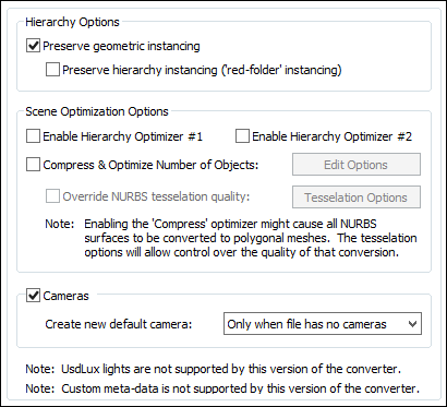
Hierarchy Options
Preserve Geometric Instancing
If this checkbox is checkmarked then the mechanism of "instancing" will be used to try and keep the size of the imported USD file as small as possible. For example, if the source file has 1000 bolts all derived from the same USD 'Prototype' node, and the 1000 items have been placed in the USD file via "instancing" then only a single copy of the geometry mesh data will be imported, but with 1000 virtual copies made of it. These virtual copy instances merely act as indexes to the original mesh primitive data instead of being full copies, which can significantly reduce the size of the final output.Note that USD files will generally treat a node as a 'Prototype' either in response to a specific per-node 'instanceable' flag, or when a node is referenced as a 'Prototype' via the 'UsdPointInstancer' node-type. Also, for a USD node marked as a Prototype, any children/sub-tree below that node is also considered part of that USD Prototype.
If this checkbox is disabled then unique and explicit copies of mesh data will be imported from the USD file regardless of whether each copy is exactly the same as previous copies already imported.
Preserve Hierarchy Instancing (Red Folder Instancing)
USD files will commonly mark an entire sub-tree of hierarchy (e.g. parent-node + all its children/descendants) as a single 'Prototype'. This allows the entire sub-tree to be Instanced by making a simple reference to the parent-node, without explicitly duplicating / copying any of the sub-tree hierarchy. In Okino software this is referred to as "Red Folder" instancing, whereby the "Red grouping folder" contains all the children hierarchy / geometry. This red folder can then be instanced N times as-if it were a single geometry item.If this option is enabled then any Prototype sub-hierarchy from USD will be recreated inside of the Okino scene graph using this "Red Folder" mechanism.
If this option is disabled then any hierarchy-nodes inside a USD Prototype will be duplicated multiple times as needed. Geometry items nested inside the Prototype will be individually subjected to the "Preserve Geometric Instancing" logic, as if they were separately-marked Prototypes (rather than being treated as sub-nodes inside a larger Prototype).
Scene Optimization Options
Enable Hierarchy Optimizer # 1, Enable Hierarchy Optimizer # 2
These options provide methods to remove redundant hierarchy nodes (NULLs, or grouping folders) from the imported file. Optimizer #1 removes runs of empty folders, as well as folders with no children. Optimizer #2 is simpler, deleting empty folders which only have 1 geometry object in them. These options can also be enabled via the Optimize hierarchy after completion checkbox found on the options dialog box of the Compress & optimize number of objects option (see below).Compress & Optimize Number of Objects
This checkbox enables one of the most important and critical scene processing functions in all of Okino software. It is an integral and core part of any Okino CAD converter, and it has been added to the USD importer for added benefits.The primary purpose of this function is to walk the imported geometry hierarchy and compress together all objects that are parented under a single folder into a one new object. For example, if you have a scene with 200 parts that are grouped under one assembly node then enabling this option will cause all such occurrences to collapse the children geometry of each imported assembly node into one object definition.
The documentation for this option can be viewed by pressing the "Options " button and then the "Help" button on the optimizer's dialog box.
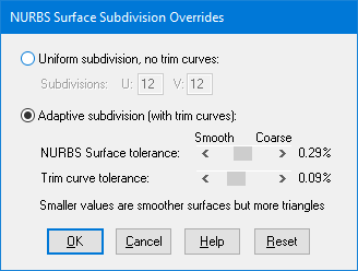
Override NURBS Tessellation Quality
When the 'Compress & Optimize Number of Objects' option is enabled then all NURBS surfaces must first be converted to polygonal meshes. The quality of the resulting meshes can be optionally controlled by enabling this checkbox and changing the NURBS tessellation override values accessible via this button:
Uniform Subdivision, No Trim Curves
This subdivision method simply subdivides the NURBS surface into a uniform mesh of U by V number of rectangular polygons. It produces the fastest tessellation of a NURBS surface but it does not allow for NURBS surfaces to be trimmed by trimming curves.Adaptive Subdivision (with trim curves)
This method adaptively subdivides the NURBS surface based on its curvature. Areas with high curvature will be subdivided more finely. This method also allows the NURBS surfaces to be trimmed by trimming curves (if there are any associated with the NURBS patches) at the expense of making the tessellation process slower.The number of polygons used to approximate the true NURBS surface (or, its smoothness) is controlled by the Surface Tolerance slider. Lower values will make the surface smoother but at the expense of a longer tessellation time and more resultant polygons. This slider represents the maximum allowable distance (tolerance) between the true NURBS surface and the tessellated polygonal surface; it is measured as a percentage of an objects maximum bounding box size. For example, if a NURBS surface is being tessellated which is 10x10x10 units in size, and this slider is set to 0.2% then the resultant polygonalized surface will not deviate from the ideal NURBS surface by more than 0.02 units (2% of 10).
The Trim Curve Tolerance slider is used to control the smoothness of the NURBS trimming curves. Lower values will make trimmed curve regions smoother, but again at the expense of a longer tessellation time and more resultant polygons. This slider represents the maximum allowable distance (tolerance) between the true NURBS curve and the tessellated polygonal curve; it is measured as a percentage of an objects maximum bounding box size (the object on which the curve lies). For example, if a NURBS surface is being tessellated which is 10x10x10 units in size, and this slider is set to 0.2% then the resultant polygonalized NURBS curve will not deviate from the ideal NURBS curve by more than 0.02 units (2% of 10).
Import Cameras
If this checkbox is checkmarked then perspective and orthographic cameras will be read in from the USD file.Create New Default Camera and Resize to Fit the Model
If this checkbox is enabled then a brand new Okino-specific 3D perspective camera will be created and made the "default" camera. The camera will be arbitrarily zoomed out to view the entire imported USD model. This new camera will not have any relation to the cameras and views contained in the source USD file. If this option is disabled then no new 3D perspective camera will be created.
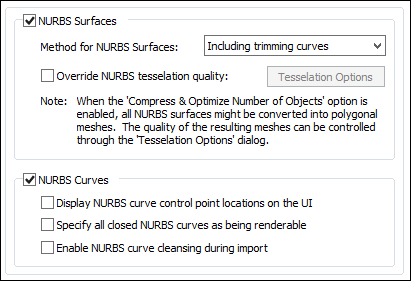
Import NURBS Surfaces
If this checkbox is check-marked then trimmed NURBS geometry will be imported from the USD file.Method for NURBS Surfaces
This combo box determines if the trimming curves are to be imported along with the base NURBS geometry.Override NURBS Tessellation Quality
Refer to the full explanation on the Selective Import Options Panel # 2.NURBS Curves
These options are used when NURBS curves are being imported from USD. In general you should never have to touch or worry about changing these options.Display NURBS Curve Control Point Locations on UI
If this checkbox is check-marked then the control point (CV) locations used by any 3D independent NURBS will be displayed. This option is only applicable when viewing imported NURBS curves within the Okino stand-alone software.Specify all closed NURBS curves as being renderable
If a NURBS curve forms a closed loop, and this option is enabled, then those curves will be flagged as being "renderable". This only has significance to the Okino stand-alone software in which case such "renderable" curves can be scanline or ray traced rendered as a 3D surface and not just a 3D curve.Also, if the curve loop is set as renderable, then it can be (optionally) converted into a trimmed NURBS 3D surface.
Enable NURBS curve cleansing during import
If this option is enabled then the NURBS curves will be "cleansed" (multiple knots removed as best can be done, and the knot vector is clamped). This option is enabled by default.
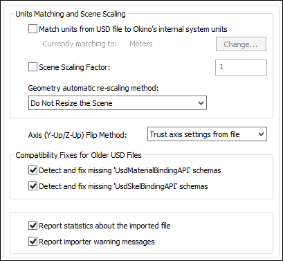
Units Matching and Scene Scaling
Match units from USD file to Okino's internal system units
These options determine what will be done when the units defined in the current glTF scene do not match those of the destination Okino internal system units (which is listed on the dialog box as the Current matching to units).If the units do not match then the importer will rescale the imported geometry based on the ratio between the glTF units and the current Okino internal system units (the Current matching to units).
If this checkbox is enabled then the importer will rescale all imported geometry so that the units of the glTF file will be made to match the current Okino internal system units. If the checkbox is disabled then the geometry will be imported unchanged and untouched, meaning that its scale may be "incorrect".
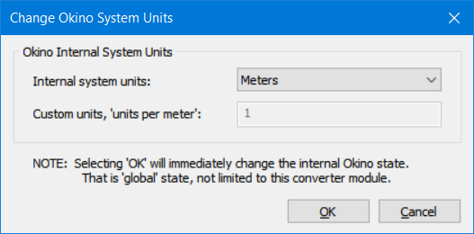
Internal System Units
This drop-down combo box specifies the current units system in effect within the internal Okino scene graph. It defaults to meters. What you need to do is select an appropriate entry from the drop-down combo box which matches the system units used by your destination program:
None No units; never do any geometry scaling Custom Custom units are in effect. See below Microinches 1e-6 inches Mils 1e-3 inches Inches 0.0254 meters Feet 12 inches Miles 63360 inches Microns 1e-6 meters Millimeters 1e-3 meters Centimeters 1e-2 meters Meters Kilometers 1e+3 meters Custom Units in "Units Per Meter"
If the drop-down "Internal System Units" combo box is set to "Custom", then this edit text control defines the "units per meter" scale factor for the custom unit system.Scene Scaling Factor = #
This option allows the imported scene to be scaled larger or smaller by a user specified amount.As examples, enter these values:
- 1.0, no scene scaling
- 1000, scale 1000 times larger
- 0.001, scale 1000 times smaller
- 4, scale 4 times larger
- 0.25, scale 4 times smaller
You can enter a value into the edit box specifying a relative scaling factor, and the model will be scaled by this factor. For example, if you enter '2.0', the model will come out twice as large.
Geometry automatic re-scaling method:
This combo box provides access to a useful mechanism which automatically rescales the imported geometry to a size best needed by other 3D software packages. This combo box can be used to automatically resize any imported model data to a useful size, such as scaled to easily fit inside a box of 2x2x2 raw working units. The various options are described as follows:Do Not Resize the Scene
No resizing is done to the imported data.Resize to 1x1x1 units
Resize to 2x2x2 units
The model data is automatically scaled up in size, or scaled down in size so that its world space extents fits inside a 1x1x1 or 2x2x2 sized unit cube.Resize to User Defined Absolute Size
The model data is automatically scaled up in size, or scaled down in size so that its world space extents fit inside a cube whose size is user defined by the type-in value shown on the dialog box. For example, if you enter the value 20 then the imported data will be resized so that its maximum extent in one or more dimensions is 20 units.Scale Larger by User Defined Factor
Scale Smaller by User Defined Factor
These options allow the imported model data to be scaled larger or scaled smaller by an absolute number. For example, if you select the larger option and enter 10 into the type-in box, then the imported model will be scaled 10 times larger during the import process.Axis (Y-Up / Z-Up) Flip Method
Okino software naturally uses a "Y" up coordinate system while USD files may use either a Y-Up coordinate system or a Z-up coordinate system. This combo box provides control as to which coordinate system the source USD file may be in.If you find that the data is oriented incorrectly after import then choose a different option from this combo box.
Compatibility Fixes for Older USD Files
Detect and Fix Missing UsdMaterialBindingAPI Schemas
Detect and Fix Missing UsdSkelBindingAPI SchemasUSD SDK rules and requirements have evolved over time. With older versions of the USD SDK, some features (such as material-assignment or skeleton-binding) was implied by the presence of certain named-attributes being present on a given node (Prim). However there have been new rules introduced to instead mandate explicit "schema" assignment to declare these features.These options allow automatic application of known "fix-up" routines to detect the related "implied" feature, and make it available via an explicit schema-assignment. This is used to preserve the behavior of older USD files, as well as remove warnings that might otherwise be generated by the newer USD SDK when encountering such "legacy" data. It should be neither necessary nor harmful for these options to remain enabled on newer USD files.
Report Statistics about the geometry file
If you enable this checkbox, statistics about the imported USD file will be displayed in the console.USD importer statistics:
   Polygon meshes imported:             1
        15452 total triangles
        14556 total vertices, 14556 total uv coords, 14556 total normals, 0 total tangents, 0 total vertex-colors
        1 UV-sets (max 1 per mesh)
        Object definitions imported:         1
        Materials (surfaces) imported:       1
        5 textures imported
        5 textures/images extracted
        Imported bounding-box has dimensions [189, 180.2, 200]
        Import took a total of 5.4s
Report Importer Warning Messages
This will print all warning messages to the importer's console. A warning does not necessarily mean that any degradation of data has occurred or that an error has occurred.Note that deselecting this option will only cause warnings to be suppressed, not statistics or errors. If there is an error that would cause the importer to abort, then this is printed to the console when the process is aborted regardless of whether or not the "Print Warning Messages" option has been checkmarked.
USD files can have different types of material shaders applied. From the perspective of Okino and our experience with USD files:
- Most USD files (from the non-Omniverse world) use the 'UsdPreviewSurface' shader. This is supported very well by this Okino USD importer for which most of its parameters are imported and mapped over to equivalent Okino PBR metallic-roughness material values and associated texture maps.
- Apple-compatible "USDZ files will import ideally as they are only allowed to use the 'UsdPreviewSurface' shader.
- A small percentage of USD files, out in the open, may fall into a category where they may use:
- Older Pixar/Disney-specific shaders (PxrDisney which predated the invention/standardization of 'UsdPreviewSurface').
- MaterialX" shader materials.
- NVIDIA/Omniverse MDL shader materials.
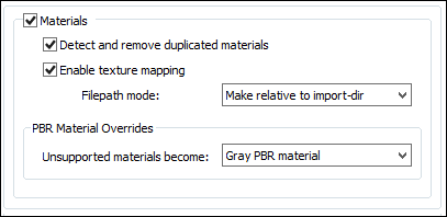
Enable Materials
If this checkbox is checkmarked then PBR materials will be imported from the USD file, in particular the 'UsdPreviewSurface', OmniPBR and OmniGlass shaders as detailed in this section.Detect and remove duplicated materials
If this checkbox is checkmarked then materials which are not associated with any geometry objects and which are deemed to be duplicates of each other will not be imported from the USD file.If this checkbox is uncheckmarked then every material of the scene will be imported from the USD file, regardless of whether they are used or not by any geometry objects.
Enable texture mapping
If this checkbox is checkmarked then 2D texture image maps that have been assigned to any of the PBR materials will be imported from the USD file as an Okino texture definition.Filepath Mode:The following PBR-centric texture channel types will be handled:
Ambient Occlusion
Base Albedo
Emission Color
Glossiness
Metalness
Normal Map
Roughness
Specular Color
Surface Opacity
Other texture channels may be added in the future, if they are not already available.
Use Absolute/Resolved Paths
The original file path of the texture map image will be used as-is (and after being resolved by the USD SDK).Make Relative to Import-Directory
The original file path will be made relative to the directory from which the USD file was imported from. Hence, the imported file path + texture image will be in a relative format and not in an absolute file path format.Use Filename Only (Strip Paths)
Texture image maps are often associated with a directory file path and filename to define their location on disk such as c:\my texture maps\brick.jpeg. By Okinos rules of data translation, it is better to not include the file path along with the texture image name. If this checkbox is checkmarked then the c:\my texture maps prefix will be stripped off the bitmap reference.PBR Material Overrides
Unsupported Materials Become:
If this importer cannot handle a specific shader type within the USD file (such as PxrDisney, MDL or MaterialX) then itll create an Okino material definition based on this combo box.Gray (Default Valued) Standard/Legacy Material
This will create a standard Okino legacy material with default values. You may want to choose this option if you know that your destination 3D file format or program does not support PBR materials.Gray (Default Valued) PBR Material
This will create a standard Okino PBR material with default values.Bright Green (for diagnostic purposes)
This will create a standard Okino legacy material with a green diffuse base color. This is provided mainly for diagnostic purposes.
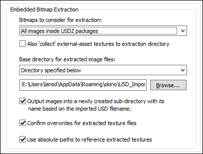
Bitmaps to Consider for Extraction
USD files allow for embedded texture map bitmap images within USDZ packages. This combo box provides control over which of those embedded images will be extracted to disk based files.All Images Inside USDZ Packages
This option will extract all bitmap images from the file to disk based files.Only Referenced Images from Inside USDZ Packages
This option will extract only those bitmap images which are actually used and referenced by the imported 3D model objects.None (Disables Embedded-Image Extraction)
No bitmap images will be extracted from the USDZ pacakge file.Also Collect External-Asset Textures to the Extraction Directory
When enabled, all external Texture files referenced by the USD file will be copied into the "texture extraction" directory. When a file has a mix of embedded-textures and external-textures, this results in all the referenced-textures existing in a single directory/location.This is primarily provided as a convenience to the end-user. It is particularly useful when the "Filepath mode" (see Materials panel) is not set to "Use absolute/resolved paths", and/or when the USD file references Textures from network-shares that might not be available later.
Base Directory for Extracted Image Files
This combo box determines where the extracted bitmap images will be saved to disk.Directory From Which this Program was Executed
The extracted bitmap images will be saved in the directory where this program began execution (which is usually the same as where this program is located on disk). This is not a preferable option since that directory would normally be read-only.Directory Where the USD Input File is Located
The extracted bitmaps images will be saved in the same directory where the USD input file was read from. This is the default.Directory Specified Below
The extracted bitmap images will be saved in the directory indicated by the static edit box. If no directory is shown, or you want to change the current directory, then the Browse button can be pressed to select the desired destination directory.Output Images into a Newly Created Sub-directory with its Name Based on the Imported USD Filename
As the text explains, this option will place all of the extracted bitmap images in their own new directory whose name will match that of the USD file. This is enabled by default.Confirm Overwrites for Extracted Texture Files
If this option is enabled then you will be prompted whether an existing image file on disk should be overwritten during the bitmap image extraction process.Use Absolute-Paths to Reference Extracted Textures
If this option is enabled then the imported scene will use absolute texture path filenames such as:C:\textures\my textures\stone.pngIf disabled then the absolute texture path will be stripped from the bitmap filename.
Over a period of 3 decades Okino came to pioneer, define and write the rule book on the cross conversion of animation data between all of the main industry 3D file formats and programs. This conversion process is based on our proprietary Arctic animation processing toolkit. The toolkit is a one stop shop for the handling, cleansing, correcting, processing, re-sampling and cross converting of all variations and types of 3D animation data. The USD importer sits on top of the Artic toolkit which ensures the accurate import and playback of USD animated entities. Ditto for the animation support in our USD exporter.
General Notes about Animation in USD:
- A traditional animation system, as defined by a DCC/Animation system of the 1980s onward (such as 3ds Max, Maya, Cinema-4D, Blender, etc), will most often use an fCurve per animated parameter, which is a linear or cubic spline curve of interpolated finite values. Thus, an explicit numeric value can be computed at any point in time from this interpolated linear or spline curve. However, USD has no such concept of interpolated spline curves. Rather, USD has explicit time-sampled data values on everything. A global setting determines if those values are to be interpreted in a linear or step manner between two time samples but not in a smooth spline-based interpolated manner.
- Similar to the DirectX file format, USD allows for an arbitrary sequence of individual affine-transforms, such as scale, rotation and translation or a single composed 4x4 transformation. Okino software excels at the import, processing and transposition of such data into explicit fCurves. If they match the traditional order of scale, rotation and translation then they will be imported as individual fCurve channels/properties. When they are not of the proper order, or there is a single composed transform matrix, then Okinos Arctic processing toolkit will use its DenseMatrixAnimation subsystem to properly transform this mess of transform data into traditional scale/rotation/translation fCurves that are compatible to legacy downstream animation programs such as 3ds Max, Maya, Cinema-4D, Blender, etc.
- NVIDIAs Omniverse has its own unique animation system which is layered on top of the core USD specification. This is not supported by this importer.
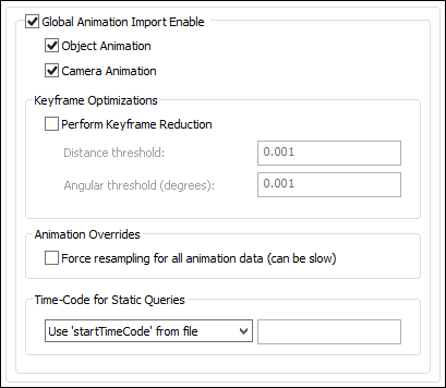
Object Animation
If checkmarked, object animation is imported from the USD file.Note: animated attributes and blend shapes are not supported.
Camera Animation
If checkmarked, camera animation is imported from the USD file.USD cameras have "focalLength", "horizontalAperture", and "verticalAperture" values, all of which can be directly and independently animated.
Keyframe Optimizations
Animation OverridesPerform Keyframe Reduction
If this option is enabled then an algorithm will be applied to the new imported keyframe lists to reduce the number of redundant keys. The type-in values determine the threshold criteria for keeping or removing a key from a list.If this option is disabled then no keyframe reduction will be done. If you want very accurate animation import then do not enable this option, or else keep the threshold values at minimum values to keep the degree of reduction low.
Distance Threshold
This numeric value indirectly controls how many redundant keyframes are to be removed from the re-sampled keyframe list. Higher values will cause more keyframes to be removed. This value is the maximum distance the new keyframe list is allowed to deviate from the original re-sampled keyframe list. Take for example a sphere that is animated along a path; if this threshold value is set to 0.5 distance units then redundant keyframes of the animated path will be removed until such point that the sphere begins to deviate by more than 0.5 units from its ideal location. In other words, if the value is set to 0.5 then you are guaranteed that the new reduced keyframe list will move the sphere along the same path in space, except that the sphere is allowed to deviate by 0.5 units from its original path. Smaller numbers will make the sphere adhere closer to its original path, but at the expense of retaining more keyframes.Angular Threshold (degrees)
This is the same as the previous numeric value except that it applies to reduction of quaternion and Angle/axis rotation keyframe lists. The value is measured in degrees. For example, if set to 5.0 then redundant keyframes will be removed from a keyframe list until such point that a rotation angle begins to deviate from its ideal angle by more than 5 degrees. Small numbers (such as 1.0 and 0.5) will cause less deviation and more precise rotation conversions, but at the added expense of retaining more keyframes.Force Resampling for all Animation Data (can be slow)
If this option is disabled then the raw keyframes will be imported directly.If this option is enabled then the Okino Artic toolkit will enable its dense matrix animation import processing pipeline. In simple terms, this will re-sample all of the imported animation data so that there will be at least one key per frame and using Bezier interpolation (plus quaternions for rotations). Since this can generate a lot of excess key frames, you may want to also enable the Perform Keyframe Reduction option on this panel.
Time Code for Static Queries
In USD absolutely everything can be animated and hence any value queried from a USD file must be evaluated at an explicit point in time (regardless of whether this importers animation checkbox is enabled or if there is any animation fCurves associated with that queried value). These options define at what point in time these static values will be evaluated by the USD SDK.Some technical background information:
- The timeCodesPerSecond and framesPerSecond metadata are fundamental baseline animation information within a USD file with the latter defaulting to 24.
- TimeCodes are the unit-less time value in USD. For any given composed scene, defined by its root layer, the TimeCode value of the TimeSamples contained in the scene are scaled to seconds by the root layers timeCodesPerSecond metadata value. If that value is missing from the USD file then this importer calls the USD SDK to query the stage's "GetTimeCodesPerSecond() value which defaults to 24.
Example USD animation Metadata:
    (
    timeCodesPerSecond = 24
    framesPerSecond = 24
    metersPerUnit = 1
    startTimeCode = 1001
    endTimeCode = 1010
    )
- Time code" essentially means "a frame" but they are set as floating point numbers rather than integers. Each time-sample has a "time code" associated with it, and each Layer has a "timeCodesPerSecond" (Layer-level meta-data). Once you have the "time-code" value and the "timeCodesPerSecond", you can convert that into "seconds". At the end of the day USD is really a system based on "seconds".
Use the Start Time Code from the USD file
This will evaluate static values based on the startTimeCode value defined in the USD file.Use the End Time Code from the USD file
This will evaluate static values based on the endTimeCode value defined in the USD file.Use this Time Code Value = #
This will evaluate static values based a specific TimeCode value (which will be converted into seconds using the timeCodesPerSecond Metadata value).Use this Frame Number Value = #
This will evaluate static values based a specific frame number (which will be converted into seconds or TimeCode using the framesPerSecond and timeCodesPerSecond Metadata values).Use Default Sentinel Value (Not Recommended) = #
Some USD files, but not all, might have a Default TimeCode value for which the USD file is specifying at what time any static queries should be computed.This option should generally not be used because there is no guarantee that a USD file will have a defined Default TimeCode value and thus querying a value such as How many polygons does this mesh have? might return this value is not defined at this TimeCode.
The Okino USD importer parses and handles the following USD/PIXAR and NVIDIA Ominiverse shaders:
UsdPreviewSurface
OmniPBR
OmniGlassThe mappings over to Okino PBR materials are detailed in the following tables:
'UsdPreviewSurface' Shading Model
https://openusd.org/release/spec_usdpreviewsurface.html
USD Property Name Description Supported? diffuseColor Albedo-Color Material-value + texture emissiveColor Emissive-Color Material-value + texture useSpecularWorkflow Controls the Okino PBRSPECULAR vs PBRMETALLIC import workflows specularColor Specular-Color. Only when 'useSpecularWorkflow' is true ("1"). Material-value + texture metallic Metalness. Only when 'useSpecularWorkflow' is false ("0"). Material-value + texture roughness Roughness. Inverted to "Glossiness" when needed to support Okino PBRSPECULAR Material-value + texture clearcoat Clearcoat-Intensity Material-value + texture clearcoatRoughness Clearcoat-Roughness Material-value + texture opacity Face-Opacity Material-value + texture opacityThreshold Opacity mask-cutoff + opacity-mode Material-value only; no texture supported IOR (Index of Refraction) IOR Not supported normal Normal-map Texture only displacement Displacement-map Texture only occlusion Ambient-Occlusion Texture only Additional notes:
- This importer fully supports shader-networks consisting of the 'UsdUVTexture', 'UsdTransform2d', 'UsdPrimvarReader_float2', and 'UsdPrimvarReader_float3' nodes as specified in the 'UsdPreviewSurface' specification. This includes various texture-scale/-bias, UV-transformations, and source-color-space data.
'OmniPBR' Shading Model
https://docs.omniverse.nvidia.com/materials-and-rendering/latest/materials.html#omnipbr
USD Property Name Description Supported? Texture? diffuse_color_constant
diffuse_textureBase Albedo Color Yes Yes albedo_desaturation Albedo Desaturation No No albedo_add Bias + Scale for Base Albedo Color Yes No color_tint Color Tint No No reflection_roughness_constant
reflection_roughness_texture_influence
reflectionroughness_textureRoughness Yes Yes metallic_constant
metallic_texture_influence
metallic_textureMetalness Yes Yes specular_level Specular Level No No enable_ORM_texture When 'true', then the "ORM_texture" overrides the Ambient Occlusion, Roughness, and Metalness maps. Yes No ORM_texture Combined Occlusion/ Roughness/ Metalness texture-map No Yes ao_to_diffuse ao_texture Ambient Occlusion Texture No Yes enable_emission
emissive_color
emissive_color_textureEmissive Color Yes Yes emissive_mask_texture Emissive Mask Map No No emissive_intensity Emissive Intensity No No enable_opacity
opacity_constantOpacity Amount Yes No enable_opacity_texture
opacity_texture
opacity_modeOpacity Map No Yes opacity_threshold Opacity Mask/ Cut-out Threshold Yes No bump_factor
normalmap_textureNormal Map No Yes flip_tangent_u Normal Map Flip U Tangent No No flip_tangent_v Normal Map Flip V Tangent (helps support OpenGL vs DirectX normal-map formats) Yes No detail_bump_factor
detail_normalmap_textureDetail Normal Map No No project_uvw
world_or_objectUVW Texture Projection No No uv_space_index UV Space Index Yes No texture_translate
texture_rotate texture_scaleTexture UV-Transformations Yes No detail_texture_translate
detail_texture_rotate
detail_texture_scaleDetail Texture UV-Transformations No No 'OmniGlass' Shading Model
https://docs.omniverse.nvidia.com/materials-and-rendering/latest/materials.html#omniglass
USD Property Name Description Supported? Texture? glass_color Glass Color (Albedo) Yes Yes depth Volume Absorption Scale No No frosting_roughness
roughness_texture_influence
roughness_textureGlass Roughness Yes Yes glass_ior Glass IOR No No thin_walled Thin Walled No No reflection_color
reflection_color_textureReflection Color (Reflectance) Yes Yes enable_opacity
opacity_constantOpacity Amount Yes No enable_opacity_texture
opacity_texture
opacity_modeOpacity Map No Yes opacity_threshold Opacity Mask/ Cut-out Threshold Yes No bump_factor
normalmap_textureNormal Map No Yes flip_tangent_u Normal Map Flip U Tangent No No flip_tangent_v Normal Map Flip V Tangent (helps support OpenGL vs DirectX normal-map formats) Yes No project_uvw
world_or_objectUVW Texture Projection No No uv_space_index UV Space Index Yes No texture_translate
texture_rotate texture_scaleTexture UV-Transformations Yes No