

| You are here: Home » Import CAD Formats » NGRAIN's 3KO Solutions |
Support: 905-672-9328 Copyright © 2026 Okino Toronto, Ontario, Canada. |

An Industry Standard, Professional CAD + DCC 3D Translation System for USD File Conversions
Okino's USD (Universal Scene Description) export conversion system intelligently and robustly converts from the worlds most popular and complex 3D programs (MCAD, AEC, DCC and Animation) into highly accurate and efficient USD binary and ASCII files. Much thought, consideration and intellect has been placed into this well defined and extensively implemented USD exporter, as can be seen by its plethora of export options.
Click for larger image.
Please also refer to the corresponding USD import converter
Main Selective # 1 Selective # 2
Lights Mesh Processing Curves
Layers Materials Bitmap Handling
File Paths Animation See also:
USD from the Perspective of Okino
Some Basic Fundamentals of USD
![[1]](/conv/exp_usd_main.jpg)
![[2]](/conv/exp_usd_selective1.jpg)
![[3]](/conv/exp_usd_selective2.jpg)
![[4]](/conv/exp_usd_lights.jpg)
![[5]](/conv/exp_usd_meshprocessing.jpg)
![[7]](/conv/exp_usd_layers.jpg)
![[8]](/conv/exp_usd_materials.jpg)
![[9]](/conv/exp_usd_bitmap_conversion.jpg)
![[10]](/conv/exp_usd_filepath.jpg)
![[11]](/conv/exp_usd_animation.jpg)
USD, by itself, is a very complex, deep and expansive file format plus associated eco-system. The Okino USD exporter goes the distance by utilizing the flexibility of USD and exposing its functionality across its 11 user-accessible panels:
- An intelligent 3D exporter that can reconfigure its USD output structure in a variety of ways to provide for flexibility in repurposing any 3D scene into a properly formatted 3D document file. Accurate conversion from all sources of primary 3D data files, including MCAD, AEC, DCC/Animation and VR/AR software applications and file formats.
- Exposed user options across 11 panels to provide you with direct control over the USD scene export process. Many options have also been added during the development process of this exporter which help smooth quirks associated with USD files, or which help create a "nice looking 3D model" in downstream USD viewers without having to tweak the source scene by hand.
- All main Okino 3D primitives will be converted and output as USD meshes with vertex normals, vertex (u,v) texture coordinates and vertex bone deformation skinning weights. Alternative outputs to trimmed NURBS surfaces or spline shapes.
- Powerful control and functionality in the export of 3D geometry and red folder instanced nodes to equivalent USD layers and asset-layers. Layers are the cornerstone of the USD file format and hence have been given proper attention and focus by this custom USD exporter:
- Support for payload layers for geometry data.
- Support for writing materials to their own material library text-based layer for easy end-user editing and tweaking of the exported material properties.
- Asset-Layers can be selectively exported from Okino geometry and red folder nodes, based on subjective merits, and a cap on the maximum number of exported asset-layers.
- Sub-layers can be written to their own sub-directory.
- A fundamental aspect of Okino software is its proper & robust implementation of material and texture map conversion. Each down-stream 3D program tends to implement materials & texture mapping differently so careful consideration must be made so that converted 3D scenes will end up looking the same, or very similar, in the source and destination programs.
- Support for Metallic-Roughness and Specular-Glossiness PBR shading models, and the optional cross conversion between them.
- Various forms of texture repacking so that a single RGB bitmap image can be encoded with several PBR shading channels (such as metallic + shininess).
- Tweaking and mixing of shading coefficients to allow for control over the appearance of the exported materials in the destination program.
- Support for multiple layers of uv texture coordinates for each exported geometry object. By default, Okino's USD exporter will minimize the number of uv texture coordinate layers written, to maximize compatibility with downstream USD viewers.
- Full geometry and hierarchy (red folder) instancing support throughout the conversion pipeline, from 3D file import to USD file export, which aids in reducing the exported file size. Many 3D users are either unaware of the importance of geometry instancing or they just gloss over it when doing 3D conversions. Retaining instancing from 3D file import to USD file export is critical to creating the most efficient and smallest of exported files. Note: Okinos geometry re-instancing system (which is enabled by default on all of its CAD importers) will create such needed instancing where none may have previously existed in the source files.
- Complete integration of Okinos 2D and 3D spline shape cross conversion engine. This is a very powerful aspect of the core Okino conversion software which allows 2D and 3D cubic spline curves, NURBS curves and spline shapes to be converted into downstream polylines or meshes. How these are output to USD is controlled via the various drop-down combo boxes on the Curve Output Options panel.
- Excellent and robust support for USD animated "skinned mesh" and skeleton export, which ties into the Okino Arctic toolkit. This allows PolyTrans to cross convert skinned mesh, animation and skeleton data between USD, COLLADA, 3ds Max, Maya, Lightwave, Cinema-4D, DirectX, glTF/glB, U3D and FBX file formats, with proper bone re-orientation, off-axis scaling removal, and so forth. Okino pioneered the animation and skeleton/bones bi-directional conversion industry.
- Mesh geometry tweaking, modification and transformations via automated operations made available by Okino's suite of polygon reduction and transformation routines. Ideal as a means to "clean up" the source meshes and apply 80-95% pre-polygon reduction to the models prior to export to USD. The global transformation dialog box allows for these variety of transformations to be applied to the entire exported scene: Center all geometry at the origin, Make all geometry sit on the Y=0 horizontal plane, Scale geometry to be no larger than XxYxZ units, Scale, Shear, Rotate and Translate.
- Object, camera and light animation output with control over interpolation type (constant or linear), resampling options and algorithms to maintain Euler continuity. Okino's Arctic toolkit provides the front-end to the USD animation export system, and thus fully utilizes its "dense matrix" keyframe resampling and reduction algorithms. Arctic also is used to ensure that all Euler animation output is properly exported (because Euler animation conversion can be fraught with problems).
- Output of scene-level and node-level meta data information to USD customData nodes, either in a nested manner, a flat manner or as strings.
- Well defined and intelligent texture map support with optional automatic resizing of all primary bitmap image file formats.
- Automatic texture bitmap file conversion to and from all key 2D bitmap image file formats. Images can be automatically resized to 2x2 to 8192x8192 pixels in size. Complete control is also provided over texture file path manipulation.
- Based on the typical Okino customer profile, this conversion system will benefit those wanting to convert from all the major MCAD programs into USD, with no data loss or introduction of shading anomalies. Commonly used source MCAD programs are ProE/Creo, SolidWorks, Autodesk Inventor, Solid Edge, Unigraphics NX, CATIA, AutoCAD, Navisworks and Revit, as well as MCAD file formats such as IGES, STEP, Parasolid, SAT, DWF, DXF/DWG and JT file formats. Okino pioneered and wrote the rule book on the conversion of super-ultra-massive MCAD/CAD data into all major down-stream 3D file formats and programs over the prior 30 years.
The USD format (Universal Scene Description) is an open 3D model and scene format designed for efficient storage and streaming of 3D asset data. It is a high-performance extensible framework and ecosystem for describing, composing, simulating, and collaboratively navigating and constructing 3D scenes.
- .usd General format in either ASCII or binary
- .usda ASCII, human-readable (crate format)
- .usdc - Binary format
- .usdz - Packaged format (a OPC-style ZIP file with a USD file + texture images).
Pixar Animation Studios originally created the USD platform (as its fourth generation variation after its Marionette & Preso systems) to improve studio-wide collaborative workflows. USD provides a concept of "scene composition", building a unified scene from potentially thousands of loosely-coupled source assets. For example, the mesh, rigging, materials, and animation for a single model might all come from different "layers" (files), each created and maintained by a different artist or department. Layers can store multiple "variants" of any given data, helping to solve problems of versioning/approval. The coupling between layers is very dynamic and loose, allowing for greater flexibility during the production process. The entire USD system is designed to facilitate a large studio making feature films, with all of the scale that that implies.
USD should be considered more of a code framework (OpenUSD) for use in group collaboration, to help with the aggregation of various 3D data sources into a unified scene through a process referred to as scene composition. A subset of that code framework provides for reading and writing USD disk-based files as well as rendering USD scenes (Hydra). The system is rather complex to implement (for software developers) and to use (from first principles) as a 3D graphics artist. The USD file format itself is not for faint of heart and is best read/written using the OpenUSD SDK + various programming APIs. More commonly used ASCII 3D file formats such as COLLADA, VRML2 and Wavefront OBJ are much easier to manipulate/understand/use on a human level basis.
In 2018 Apple adopted a subset of USD technology as part of their own AR/VR initiative. Most 'USDZ' files that can be found online are related to this specific subset of USD functionality. For example, an Apple-compatible USDZ file can only contain a single 'layer' file, bundled with a set of embedded textures. As a file-format, these USDZ files are used for web-based asset-delivery to an AR/VR viewer, largely ignoring the collaborative-workflow features built into USD. This is why youll see 'USDZ' files commonly used by Apple compared to the more widely used and adopted glTF or FBX by other software vendors.
The file format was made open sourced in 2016 by Pixar and supported by NVIDIA as OpenUSD - OpenUSD.org. Their Omniverse framework is built upon OpenUSD but with many of their own extensions, such as their own implementation of animation for USD.
Overall, from its 40 year history of 3D converter development and experience, Okino considers USD to be a highly complex file format and ecosystem to both implement, roll-out and support in the long term (along the lines of Okinos STEP, IFC and Microstation DGN MCAD conversion systems).
USD does have its place within the 3D industry but other formats such as glTF, COLLADA, FBX, VRML2 and Wavefront OBJ are more ubiquitous for general 3D model asset and scene sharing, whereas USD excels more at collaborative work scenarios. USD also comes with versioning concerns that many other file formats don't suffer from at all or as much. One cannot use the words better or best when it comes to the plethora of 3D file formats which exist as each can only be properly differentiated within its related usage context.
The core flexibility that makes USD so attractive can also make it difficult to use. The collaborative workflows operate more smoothly if the overall layer-structure is decided in advance, based on the team's requirements. USD is an "enterprise-grade" tool that can make life easier for large teams operating at-scale but can risk adding too much complexity for smaller teams (or individuals). The OpenUSD framework is incredibly extensible, but that also risks fragmentation of the user-base. For example, there are plugins to achieve either MaterialX or NVIDIA MDL materials but not all consumers of USD files will support those extensions.
USD organizes data into hierarchical namespaces of Prims (short for primitive). A Prim is the smallest atomic object that can be defined, customized and manipulated within USD. Prims are technically containers of Metadata, Properties, and other Prims.
In addition to child Prims, each Prim can contain Attributes and Relationships, collectively known as Properties. Whereas Prims provide the organization and indexing for a composed scene, Properties contain the real data. Attributes have typed values that can vary over time. Relationships are multi-target pointers to other objects in a hierarchy. Attributes are the workhorse of storing actual data inside a Prim and are often defined as part of Schemas to make it easier to access context-relevant data from within an instance of that Type.
Both Prims and Properties can also have (non-time-varying) Metadata. Metadata is the lightest-weight form of name, value scene description; it is light because unlike Attributes, Metadata cannot be time-varying, and because Prims and Properties can possess Metadata, but Metadata cannot itself have Metadata.
Prims and their contents are organized into a file abstraction known as a Layer. Layers are a component of the collaborative nature of USD. Each layer in USD signifies a users opinion on assets inside a stage. Layers can override other Layers. A Layer contains zero or more Prims, that in turn describe Property and Metadata values. Each layer possesses an identifier that can be used to construct references to the Layer from other Layers.
A USD Stage provides the mechanism to view all the assets in a current USD scene. The Stage is the USD abstraction for a scene graph derived from a root USD file, and all of the referenced/layered files it composes (in a hierarchical parent/child order).
You can stack USD Layers together using the subLayers composition arc, and the composition engine will resolve the data contained in such ordered (nestable) LayerStacks similarly to how layers in Photoshop are composed. This is one of the more powerful aspects of using USD, whereby the USD composition engine will resolve the resulting graph in a predictable way; a stronger Layer will override any weaker Layers.
VariantSets allow an asset creator to bundle different multiple variations of an asset all into a single package with a variant selector that downstream asset consumers can switch, non-destructively, in stronger layers to change the variation they desire; any prim can define multiple VariantSets, which can vary along dependent or independent axes.
3D file formats are often associated with a major a minor version. For example, there is glTF v1.0 and glTF v2 formats. There is VRML 1 and VRML2. There is FBX v5 (Kaydara), FBX v6 (Alias|Wavefront) and FBX v7 (Autodesk). However, that concept has not been rolled over into the USD framework, at least at the time of this writing.
Since USD follows a "large studio" model it does not seem to pay much attention to backwards-compatibility of existing files. In a large studio setting, all machines would typically have software fixed to a given version-number across the entire production. If software was updated during production, it would likely be done in a controlled roll-out, supervised by IT professionals, with attention paid to any data-changes that needed to be made for compatibility. The USD file format itself does not provide versioning information that is found in other commonly used 3D format formats. The USD SDK itself does not provide any versioning information. So, as the data-model morphs over time (such as revisions made by Pixar) there is no way to track what automatic-updates might be applicable.
One must firmly keep in that that USD is not just a 3D file format but rather a large and complex framework. That framework, for example, allows for internal and external plug-ins to be added for increased functionality, such as to handle MaterialX shader files, Wavefront OBJ files, FBX files, etc. Higher level consumers and users of that framework do not generally care where the data came from -- they simply consume the unified view provided by the USD frameworks data-model (Prims + Attributes + Properties + Meta-data).
Because the USD framework and SDK is such a "constellation of plug-ins" in the first place, it is very difficult to lock down any meaningful version-number. Hypothetically, you might be running off the same SDK version "USD XX.YY" as with your co-animator, but do you have all the same plug-ins installed? Do you have the same MaterialX plug-in installed? Did one of you drop in a third-party "asset-resolver" plug-in so that you can reference assets that live inside an "Autodesk Vault" server? Or maybe another animator's studio wrote their own file format plug-in so that they can load up the output of their custom particle-system simulation as time-varying meshes inside USD. These issues all complicate the concept of USD file and project versioning.
In theory, if one carefully tracked USD data-model changes over time, one could possibly detect the rough "era" of a given USD file. However, that would not be particularly easy to do and such information would not be overly helpful. In a best-case scenario, Okinos USD importer might be able to say "Note: your file might be 5+ years old and as such might not load properly" but there are not many cases where we could make that distinction amongst different vintages of USD source files.
Having both USDa/USDc and USDZ file formats may be confusing to many people. This section will provide a short overview to differentiate them.
The OpenUSD file format specifications home page for USDZ succinctly explains why Apple chose to develop the much simplified USDZ subset. Simply put, USD by itself is just too complex for consumer software applications, such as Apples VR/AR consumer initiative. As they state:
Part of USDs appeal is its ability to create a 3D scene by composing many modular data sources (files) together into successively larger and larger aggregations. While very useful within content creation pipelines, this aspect can be a very large hindrance to using USD to deliver assets in the form that they have been built up. In particular, even though USD does provide several means of flattening multiple USD files into a single file, there is, by design, no mechanism for representing images/textures as the scene description encodable in USD files. Content delivery is simplified and useful on a broader range of platforms when the content is:
- A single object, from marshaling and transmission perspectives
- Potentially streamable
- Usable without unpacking to a filesystem
In that manner, a USDZ package is an uncompressed zip archive that is allowed to contain the following file types:
- USD 3D file: .usda, .usdc, .usd (presently, only one such file)
- Images: PNG, JPEG or EXR
- Audio: M4A, MP3, WAV
The key intention of a USDZ package is to provide perfectly reproducible results in arbitrary consuming environments.
USD differs from similar formats such as COLLADA, FBX, glTF and Okino .bdf format based on why Pixar chose to create it and how they utilize it within their 3D production pipelines.
Key differences of USD over other similar 3D file formats:
- A single USD scene can be collaboratively changed by multiple animators at the same time and at remote locations (such as via NVIDIA Omniverse and its connectors to common third party DCC/Animation packages).
- As claimed on the OpenUSD WEB site:
- USD addresses the need to robustly and scalably interchange and augment arbitrary 3D scenes that may be composed from many elemental assets.
- USD provides for interchange of elemental assets (e.g. models) or animations. But unlike other interchange packages, USD also enables assembly and organization of any number of assets into virtual sets, scenes, shots, and worlds, transmitting them from application to application, and non-destructively editing them (as overrides), with a single, consistent API, in a single scenegraph. USD provides a rich toolset for reading, writing, editing, and rapidly previewing 3D geometry, shading, lighting, physics, and a growing number of other graphics-related domains. In addition, because USDs core scenegraph and composition engine are agnostic of any particular domain, USD can be extended in a maintainable way to encode and compose data in other domains.
- Like many other interchange packages, USD provides a low-level data model that stipulates, at a file format level, how data is encoded and organized, plus a (extensible) set of high-level schemas that provide meaningful APIs and organization for concepts like a mesh or a transform. With such a foundation one can create asset definitions with geometric, material, lighting, and other properties. But USD goes further to provide a freely combinable set of Composition Arcs that can be used to package, aggregate, vary, and override primitive elements and assets, with a high-performance runtime evaluation engine, embodied in a compact scenegraph known as a Stage, for resolving the resulting composed scene description and extracting (and authoring) data from it.
- USDs most basic composition arc, the subLayers operator, facilitates multiple artists in different departments, or within the same department, to simultaneously work on the same asset or scene, by allowing each artist to work in their own file (called a Layer), all of which will be combined and resolved in a strength ordering clearly specified in the USD files themselves. This ability is not a magic bullet that can automatically adjust shading data in a stronger layer when the modeling artist changes the topology of geometry defined in a weaker layer, but it allows each artist to work independently without erasing or editing any other artists work, and helps to provide a clear audit trail of changes that aids in addressing problems like the changing-topology problem.
This panel contains the USD export options which are most often used or should be considered during an export process.
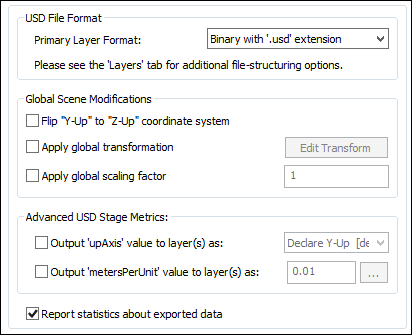
USD File Format Primary Layer Format
This combo box allows you to choose which variation of a USD file is to be output.Please refer to the Layers section for additional file-structuring options.
Binary file with .usd extension
Binary file with .udsc extensionThese combo box options represent the most common export formats for USD. Both will output the same binary file but with different file extensions. The .usdc is the Crate format version of USD.Text file with .usda extension
This will export the USD file as ASCII, human-readable text (crate format).Global Scene Modifications
Flip "Y-Up" to "Z-Up" coordinate system
If this checkbox is enabled then a Y-Up to Z-Up coordinate system flip will be applied to the exported data. Okino software uses a Y-Up coordinate system.By policy, all of Okinos CAD importers implicitly convert from a Z-Up coordinate system (such as from AutoCAD) into the Okino Y-Up coordinate system. As such, if you find that a 3D model appears flipped on its side in the USD file viewer then please enable this checkbox on the USD exporter, or, enable the equivalent Flip Y Up checkbox on the Okino CAD importer.
Apply global transformation
If this checkbox is enabled then a general purpose global transformation will be applied to each exported USD scene. This new transformation matrix will be applied to the root node in the exported USD file.This option will allow you to, for example,
- Re-center all of the geometry so that it is centered at the origin (0,0,0) in the USD file.
- Move all of the geometry so that it is sitting on the Y=0 (XZ) horizontal plane.
- Auto-scale the geometry so that it is no larger than a specific bounding box size.
- Scale the scene by a (X, Y, Z) value.
- Shear the scene by a (X, Y, Z) value.
- Rotate the scene by a (X, Y, Z) value.
- Translate the scene by a (X, Y, Z) value.
The transformation can be edited by pressing the "Edit Transform" button which will cause the following global transformation dialog box to appear:
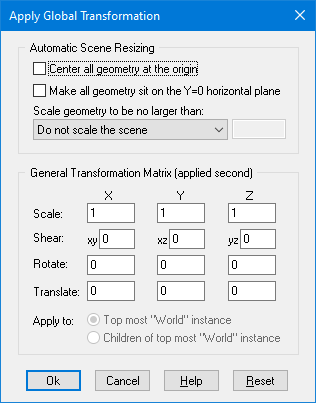
The transformation matrix will be computed in two phase: (1) the transformations specified in the top "Automatic Scene Resizing" section, then (2) the single transformation specified in the "General Transformation Matrix" section.
The values on the dialog box are described as follows:
Automatic Scene Resizing
Center all geometry at the origin
If this checkbox is enabled (checkmarked) then all the geometry data will be positioned so that it is centered about the origin. If disabled then the geometry will not be repositioned.Make all geometry sit on the Y=0 horizontal plane
If this checkbox is enabled (checkmarked) then the geometry will be repositioned so that it is sitting flush with the top of the Y plane (the horizontal plane).Scale geometry to be no larger than:
This option allows the geometry data to be automatically rescaled if it is too large. If set to 'Do not scale the geometry' then no scaling will be done. If set to '1x1x1 units' then all the objects will be scaled smaller should they exceed 1x1x1 units in total size. Likewise for the '2x2x2 units' option. If set to 'User defined maximum size' then the maximum size of all the objects can be set using the type-in numeric box. The default is '2x2x2 units'.Although not quite the same, if the option is set to Use Absolute Scaling Factor then all objects exported to the USD file will be scaled absolutely by the user specified value. Thus, if you set the type-in value to 0.25 then all objects will be made 4 times smaller and if the value if set to 4 then all objects will be scaled 4 times larger. This is useful is you are converting a variety of different models to USD format and you want them all uniformly scaled with the same scaling factor.
Transformation Matrix Values
Translate X, Y, Z
This applies a 3D translation by the specified amounts in the X, Y and Z dimensions.Scale X, Y, Z
This applies 3D scaling in the X, Y and Z dimensions. All 3 scale factors must be non-zero. Values above 1.0 will make the scene larger (2.0 will double the size of the scene) while values less than 0 will make the scene smaller (0.5 will half the size of the scene).Shear XY, XZ, YZ
This applies a linear shear in one of 3 directions:XY will shift all points in the X direction by the specified amount in proportion to the distance the points are located along the positive or negative Y axis. For example, using a value of 2.5 will shear all points by 68 degrees in the positive X direction; in other words, for every unit increase in the Y direction the X points will be shifted by 2.5 units.
XZ will shift all points in the X direction by the specified amount in proportion to the distance the points are located along the positive or negative Z axis.
YZ will shift all points in the Y direction by the specified amount in proportion to the distance the points are located along the positive or negative Z axis.
Rotate Around X Axis
Rotate Around Y Axis
Rotate Around Z AxisThis applies a rotation about the X, Y and/or Z axes. The rotation angle is restricted to the range -360 to 360 degrees. The angle of rotation is counter-clockwise when viewed from the positive to negative axis of rotation.Apply global scaling factor = #
This value allows a custom scaling to be applied to the overall exported scene. For example, if set to 10.0 then the entire exported scene (geometry, lights and cameras) will be scaled 10 times larger.Advanced USD Stage Metrics
Unlike with the "Global Scene Modifications" (see prior section) which actually modify the actual underlying data, these "USD Stage Metrics" options just modify the meta-data entries that describe what/how the data was stored.Output upAxis value to layer(s) as:
Declare Y-Up [default]
Declare Z-UpIf this checkbox is enabled then stage-/layer-level meta-data will be output to the USD file specifying the implied Up-Axis of the exported file. This information is optional and may be ignored by the destination program.
For example, if the "Flip "Y-Up" to "Z-Up" coordinate system" checkbox is enabled and this combo box is set to Declare Z-Up" then Omniverse will load the USD file as having a Z-up orientation, with its "grid" along the XY-plane (rather than the default XZ-plane)
Output metersPerUnit value to layer(s) as: ###
Okino software is written so that all of its 3D importers and other plug-in systems recognize and respect the unit of measure associated with each source 3D file (if and where technically possible). For example, SolidWorks and Microstation files are usually in millimeters; 3ds Max and SketchUp files are usually in inches; Maya files are in cm, and so on.If this checkbox is enabled then stage-/layer-level meta-data will be output to the USD file specifying the meters per unit and the units of measure which can then be utilized by the destination USD-centric program (such as Omniverse).
Without this checkbox enabled, technically, USD should internally default to 0.01.
This information is optional and may be ignored by the destination program.
Report statistics about exported data
If this checkbox is checkmarked then statistics will be output after the USD file has been exported, which looks like this:USD Export Statistics: Number of meshes = 54 Number of polygons = 9395 Number of mesh vertices = 5711 Number of vertex normals = 5711 Number of lights = 2 Number of directional lights = 2 Number of perspective cameras = 4 Number of orthographic cameras = 5 Number of materials = 42 Number of group nodes = 174 Number of animation curves = 336 (88786 total keys)
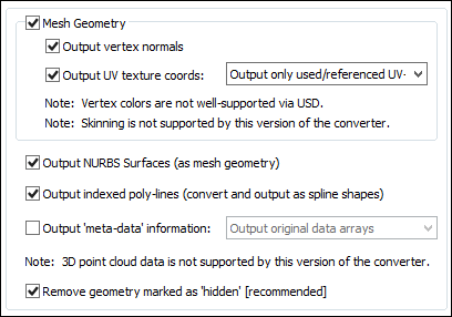
Output Mesh Geometry
This checkbox should not, in general, need to be disabled. It controls whether polygonal mesh data will be output to the USD file. This is the main and primary geometry type used by the USD software.Technically, USD supports these polygon types: triangles, quads, n-sided, convex and concave. Okinos 3D geometry sub-system supports all of these types.
Note: vertex colors are not well supported by the USD file format.
Output vertex normals
If this checkbox is checkmarked then vertex normals will be exported along with the mesh geometry. Vertex normals are required to provide the "smoothing" information for a mesh model.Disabling this option may make for smaller files but at the expense of making the models appear faceted.
Output vertex UV texture coordinates
If this checkbox is checkmarked then (u,v) vertex texture coordinates will be exported along with the mesh geometry. These are needed to define the mapping of 2D texture images onto the 3D mesh geometry. Disabling this option may result in smaller USD files, but at the expense of not being able to map 2D texture images onto the mesh geometry. Materials make reference to the UV sets associated with geometry items.Output all UV-sets
This option will output all UV sets associated with a mesh geometry object even if some of them are not used by related materials.Output only used/referenced UV-sets
This option will only output those UV sets of a mesh geometry object which are referenced by one or more materials.Minimize UV-set data via Quilting
In simple terms this option will compress a number of different UV-sets down to a lesser number by exporting only those UVs that are actually used, not those that are actually defined in the 3D scene.Technically
In the case where a mesh has N different materials assigned, these might reference up to N different UV-sets. However, each individual polygon will only need UV data from one UV-set. We can effectively compress data in this situation by building a new "quilted" UV-set, which can be shared between all N assigned-materials. Each polygon in the "quilted" UV-set is assigned the UV-data that is actually used by the material assigned to that polygon.
This generalizes to having K different texture-layers per material; the first layer will use the quilted-uv0, the second-layer will use the quilted-uv1, etc. In a case where some materials use more layers than others (on the same mesh), then some of the higher quilted-uv%d sets will have '-1' indices for some polygons.
Output Skinning Weights & Bones/Skeletons (Mesh Deformation)
Okino invented and pioneered the concept of skinning/skeleton cross conversions amongst all the major DCC/Animation and related 3D file formats, and as such are expected to have that same level of excellent support in this exporter. The USD importer does have it implemented.
"Mesh skinning" is the process of deforming a single skin mesh with a skeleton of bones or any hierarchical set of transform nodes. The contribution of each bone of the skeleton to the deformation of a vertex in the mesh is controlled by vertex weights. More information can be found online at this Okino WEB page.
If this option is enabled then a single polygonal mesh will be bound to one or more secondary objects (deformers, such as bones) via transformation matrices and weight values in the USD file.
Only skinned meshes are supported for export, not skinned NURBS surfaces or skinned curves.
Typical sources of skinned mesh data (and which are supported by Okino software) are 3ds Max, Maya, LightWave, Cinema-4D, Softimage (XSI), FBX, glTF/glB, COLLADA, DirectX, U3D and USD.
Oddly, in a manner similar by which the older 1990s LightWave software works, the USD skeleton node hierarchy is defined within a single Prim called 'UsdSkelSkeleton'. One or more geometry mesh Prims then make reference to that single 'UsdSkelSkeleton' Prim via its "skel:skeleton" property on the geometry Prim. This contrasts with most other 3D file formats whereby the skeleton hierarchy is defined as an independent child/parent hierarchy of 4x4 transformation nodes that are visually presented in the user interface as a hierarchy of bones or skeletons+joints; one or more polygonal meshes link their vertices over to one or more bone/skeleton 4x4 transform nodes of its associated skeleton.
Output NURBS Surfaces (as polygonalized mesh geometry)
This check box determines whether trimmed NURBS geometry within the Okino database will be exported to USD as tessellated mesh data.Output Indexed Poly-Lines (convert and output as spline shapes)
This check box determines whether linear polylines geometry within the Okino database will be exported to USD as linear spline shapes.Output Meta-data Information
Most CAD file formats, and programs like 3ds Max and Maya, allow "meta-data" to be associated with each node of a 3D scene. Enabling this option will output such meta-data information to the USD file. Such data is fully supported by Okino software, from import to export.Note, however, based on our own experience, there are many ways in which meta-data can be passed around within a USD file and there appears to be little agreement between the various 3D DCC/Animation packages as to how they deal with meta-data (ie. for 3ds Max, Maya and Blender). There is no "standard" for transferring meta-data within USD. Okino has chosen to export its meta-data as customData nodes and not "userProperties" (as chosen by Blender).
The meta-data is extracted from the Okino global scene meta-data and also the per-instance meta-data (such as on geometry, lights, cameras and materials).
This option is turned off by default, as meta-data can increase file-size, and most USD loaders/viewers will either not care for this data nor know what to do with it.
The following internal Okino scene graph meta data types are supported when exporting to USD: strings, shorts, ints, floats, colors, vectors, double precision vectors, 4x4 matrices, 4x4 double precision matrices, time, double precision floats, 4 valued vectors, and 4-valued double precision vectors.
Output original data arrays
In this mode the nested meta-data arrays (such as for matrices) will be output without modification.The following is a USD example of such meta-data output:
customData = {
    dictionary custom_properties = {
        string Binary_data = "\x10 0@"
        float3 a_32_bit_color = (0.1, 0.2, 0.3)
        float a_32_bit_float = 1.23
        matrix4d a_32_bit_float_matrix =
            ( (1, 0, 0, 0), (0, 1, 0, 0), (0, 0, 1, 0), (0, 0, 0, 1) )
        float3 a_32_bit_float_vector = (1, 2, 3)
        float4 a_32_bit_float_vector4 = (1, 2, 3, 4)
        int a_32_bit_integer = 65535
        double a_64_bit_double = 1.23
        matrix4d a_64_bit_double_matrix =
            ( (1, 0, 0, 0), (0, 1, 0, 0), (0, 0, 1, 0), (0, 0, 0, 1) )
        double3 a_64_bit_float_vector = (10, 20, 30)
        double4 a_64_bit_float_vector4 = (10, 20, 30, 40)
        float[] array_4_floats = [0, 1, 2, 3]
        int[] array_4_short_integers = [0, 1, 2, 3]
        int[] array_4_tick_times = [0, 1, 2, 3]
        int short_integer = 32767
    int tick_time = 12345
    }
}
Output 'flattened' data arrays
In this mode the nested meta-data arrays (such as for matrices) will be flattened into single arrays during output:customData = { dictionary custom_properties = { string Binary_data = "\x10 0@" float[] a_32_bit_color = [0.1, 0.2, 0.3] float a_32_bit_float = 1.23 float[] a_32_bit_float_matrix = [1, 0, 0, 0, 0, 1, 0, 0, 0, 0, 1, 0, 0, 0, 0, 1] float[] a_32_bit_float_vector = [1, 2, 3] float[] a_32_bit_float_vector4 = [1, 2, 3, 4] int a_32_bit_integer = 65535 double a_64_bit_double = 1.23 double[] a_64_bit_double_matrix = [1, 0, 0, 0, 0, 1, 0, 0, 0, 0, 1, 0, 0, 0, 0, 1] float[] array_4_floats = [0, 1, 2, 3] int[] array_4_short_integers = [0, 1, 2, 3] int[] array_4_tick_times = [0, 1, 2, 3] int short_integer = 32767 int tick_time = 12345 } }Output meta-data as strings only
This combo box option will output all meta-data types (numbers and all) purely as string values.To follow on with the above examples, this would result in output such as:
customData = {
    dictionary custom_properties = {
        string Binary_data = "\x10 0@"
        string a_32_bit_color = "ok_color:
            (0.100000, 0.200000, 0.300000)"
        string a_32_bit_float = "ok_float: 1.230000"
        string a_32_bit_float_vector = "ok_vector:
            (1.000000, 2.000000, 3.000000)"
        string a_32_bit_float_vector4 = "ok_vector4:
            (1.000000, 2.000000, 3.000000, 4.000000)"
        string a_32_bit_integer = "ok_int: 65535"
        string a_64_bit_double = "ok_double: 1.230000"
        string array_4_floats = "ok_float:
            0.000000; 1.000000; 2.000000; 3.000000"
        string array_4_short_integers = "ok_short:0; 1; 2; 3"
        string array_4_tick_times = "ok_time:0; 1; 2; 3"
        string short_integer = "ok_short: 32767"
        string tick_time = "ok_time: 12345"
    }
}
Remove geometry marked as hidden (recommended)
Okino mesh geometry objects have a hidden state associated with them. It is fairly common to import a CAD file which has objects marked as being hidden.USD does have a "hidden" flag but it hides an entire sub-hierarchy tree (similar to how Maya works). In Okino software there is a geometry/instance and grouping hidden flag for each node as well as an inherit hidden flag which specifies whether the hidden state for a node should be propagated to children.
If this option is enabled (checkmarked) then such hidden geometry will not be exported, thus leading to smaller USD files. It is highly recommended that you keep this option enabled as it solves an edge case with red folders and their visbility.
However, there may be cases whereby you need the entire source 3D scene to be exported, hidden and all. In such cases, this checkbox should be disabled. This will cause all geometry which is normally hidden within the Okino scene graph to be fully visible within the USD scene.
This panel controls the output of entities to the USD file.
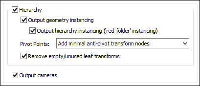
Output Hierarchy
If this option is enabled (checkmarked) then the hierarchical relationship of objects in the scene will be exported using nested USD nodes. If this option is disabled then no hierarchy will be output and all mesh objects will be exported in flattened world-space coordinates.Output geometry instancing (use instancing to reduce file size)
If this checkbox is checkmarked then the mechanism of "instancing" will be used to try and keep the size of the USD file as small as possible. For example, if the source scene has 1000 bolts all derived from the same mesh primitive data, and the 1000 items have been placed in the Okino scene graph via "instancing", then during export to USD only a single copy of the geometry mesh data will be exported to USD, but with 1000 virtual copies made of it. These virtual copy instances merely act as indexes to the original mesh primitive data instead of being full copies, which can significantly reduce the size of the final output.If this checkbox is disabled then unique and explicit copies of mesh data will be output to the USD file regardless of whether each copy is exactly the same as previous copies already exported.
Output Hierarchy Instancing (Red Folder Instancing)
USD files will commonly mark an entire sub-tree of hierarchy (e.g. parent-node + all its children/descendants) as a single 'Prototype'. This allows the entire sub-tree to be Instanced by making a simple reference to the parent-node, without explicitly duplicating / copying any of the sub-tree hierarchy. In Okino software this is referred to as "Red Folder" instancing, whereby the "Red grouping folder" contains all the children hierarchy / geometry. This red folder can then be instanced N times as-if it were a single geometry item.If this option is enabled then any "Red Folder" sub-hierarchy within the Okino scene graph will be recreated in the USD file as a Prototype sub-hierarchy.
If this option is disabled then any hierarchy-nodes inside an Okino "Red Folder" sub-hierarchy will be duplicated multiple times as needed. However, geometry items nested inside a "Red Folder" will be individually subjected to the "Output geometry instancing" logic (see above).
Pivot Points
Pivot points are a fundamental component of an animation system. In the realm of the Okino animation system pivot points define a local 3D coordinate system in the space of an object about which the scale, rotation and translation animation function curves will be applied. The pivot point in Okinos scene graph is defined by a 3D point in space and a local coordinate system defined by 3 orthogonal XYZ axes; the pivot point is itself defined relative to the local coordinate system of the underlying mesh or geometry data.For example, the virtual pivot point and its orientation axes allow a robot arm to properly rotate around its elbow joint instead of some other awkward point of the object. Any such animation placed on the robot arm will then naturally occur relative to this elbow joint.
A basic problem is that not all destination animation programs have the same concept of pivot points as with a source animation program. Some programs are more complex, some much simpler. The following options control how Okino software performs this mapping.
First, some rules need to be defined for the following explanations. Pivot point processing only needs to be done under these circumstances for the two Minimal modes:
1) The pivot point 4x4 matrix has a non-zero origin or non-aligned orientation axis. In other words, it has something interesting in it, or
2) The instance has animated channels associated with it, or
3) The (static) transformation matrix associated with an instance has off-axis scaling within it. Off-axis scaling is where rotation comes before scaling, which is basically an illegal or poorly supported situation for most 3D programs.For a grouping folder (an Okino empty instance), which is deemed to have a valid pivot point matrix, a new child anti-pivot node is added to the exported hierarchy tree - the child node is assigned the inverse pivot matrix and the original parent transform node gets the animation data. This properly applies the anti-pivot effect to the subsequent children in the tree.
The following options specify how the Okino pivot point information is exported for instance-geometry nodes:
Embed minimal pivots in geometry data
Logic same as the next option below except that the processing mode will only be invoked when one of the 3 rules explained above are valid. This leads to a cleaner conversion.Embed pivots in *all* geometry data
Logic regardless of the 3 rules explained above, this processing mode will be invoked on ALL instance-geometry nodes if any of them have a non-identity pivot matrix.The inverse pivot matrix is multiplied into the raw mesh geometry vertices. In other words, the messy pivot point problem is made to disappear by having its 4x4 matrix physically multiplied into the mesh geometry vertices.
Add minimal anti-pivot transform nodes
Logic same as above except that the processing mode will only be invoked when one of the 3 rules explained above are valid.This is the default option since (1) it results in the fewest changes to the output hierarchy tree and (2) it does not physically affect the mesh geometry coordinate data.
Output all anti-pivot transform nodes
Logic regardless of the 3 rules explained above, this processing mode will be invoked on ALL instance-geometry nodes if any of them have a non-identity pivot matrix.A new "anti-pivot" dummy node is introduced into the exported hierarchy tree, between the mesh geometry object and the parent transform node (which has the animation on it). The inverse of the Okino pivot point matrix is assigned to the transformation matrix of this new anti-pivot dummy node. This new anti-pivot node acts to pivot-in the geometry vertices prior to the animation data being applied to the geometry.
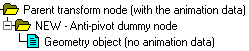
Thus, this mode splices in the pivot point matrix into the destination hierarchy tree as a new transformation node rather than to multiply the pivot point matrix into the raw mesh geometry, as with the other modes.
Ignore all pivot point data (can cause problems)
This option prevents pivot point information from being output to the USD file. Normally you would never want to enable this option.Remove empty/unused leaf transforms (empty grouping nodes)
If an exported NULL/grouping node has no children, is not a joint of a bone hierarchy and has no animation on it, then such useless grouping/NULL nodes are deleted during the export process if this checkbox is enabled..If this option is disabled then such useless grouping/NULL nodes are retained during the export process into USD and not deleted. You will want to disable this checkbox if you are exporting a file of NULL nodes and you wish all of them to be exported without pruning.
Output Cameras
If this checkbox is checkmarked then all perspective and orthographic cameras will be output to the USD file as free (non-targeted) cameras. Adjusted near and far clipping plane values will also be output.
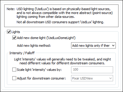
This panel controls the output of lights to the USD file.
Notes:
- For 95% of the people using this USD exporter, you will probably want to keep the export of lights disabled (which is the default). And for those sourcing from MCAD data, there will be no lights to consider from such files.
- It is probably better (from a user experience standpoint) to not export any lights to the USD file and to allow USDVIEW or Omniverse to decide on their own lighting policy for scenes with no lights in them.
- From Okinos development perspective, USD lights are a mess to deal with and to transfer from one program to another. They are not easily exported as one would normally expect with traditional punctual lighting (such as point, directional and spot lights).
- USD lighting (UsdLux) is based on physically-based light sources and is not always compatible with the more abstract (point-source) lighting coming from other 3D data sources and which are standard within Okino software. For example, light falloff follows strict real-world/PBR rules but there are additional "exposure" and "radius" values that also influence the level of illumination.
- Not all downstream USD file consumers support UsdLux lighting.
- Note, Omniverse seemingly breaks all the USD rules: USD defines the light-intensity as defaulting to '1.0' but Omniverse needs lights with an intensity around '1000' or else they show practically no illumination. Also, they require a 'radius' of 50 instead of the default 0.5. Any lights added within Omniverse will have those new-defaults, but lights with "no authored values" will not pick up those local-defaults.
- This exporter attempts to export reasonable lighting to the USD file but it is expected that the user of this data will tweak and modify such lighting in their destination program (such as the lighting intensity, fall-off curves, cone angles, etc). However, from the perspective of Okino, we are transferring the more important information of such lighting to the USD file, in particular the light transform information and any related animation data.
Add new dome-light (UsdLuxDomeLight)
Most Okino 3D exporters have an option called Add new Lights and an associated combo box of lighting configurations to choose from. However, those forms of punctual lights have no place in the world of physically-based lighting used by USD. Instead a UsdLuxDomeLight can optionally be exported. A dome-light in USD is basically a sky-box/IBL form of distant-environmental-light.Note: you may want to disable this option for export to Omniverse as it will apply reasonable default lighting when there are no lights in the scene.
Add New Lights Method
This combo box determines how the new dome light is to be added into the exported USD file.Intensity / Falloff Options
Light intensity values will generally need to be tweaked during export and might need different values for different downstream USD file consumers.Scale light intensity values by #
USD defines a PBR-based lighting model which relies on the assumption of "physically accurate" light-definitions. In particular, for this export option, it means that USD strictly uses quadratic light drop-off attenuation (e.g. "1/distance^2" as the light's attenuation). This is incompatible with how light attenuation has been defined for decades in many other 3D software programs (which may often use linear and/or exponential light intensity drop-off vs. quadratic).This type-in value is provided as a tweaking parameter to increase or decrease the overall lighting brightness in the destination USD viewer. Values greater than 1.0 will make the scene brighter while values below 1.0 (such as 0.5) will make the scene darker. As a suggestion, you may want to change the value by factors of 10.
This exporter will auto-adjust the lighting intensities from the source 3D file to be a good approximation to the intensity and attenuation values expected of a USD file viewer. However, since this mapping is quite general and approximate, the final scene may appear too bright or too dark. The type-in value will allow you to make such manual adjustments.
Adjust for downstream consumer
Enabling this option will force specific values on the exported lighting so that they will appear reasonable within either PIXARs USDView or NVIDIAs Omniverse. These values were chosen by Okino based on our own experience with exporting 3D scenes into both of these programs.PIXAR USDView
No changes or adjustments will be made.NVIDIA Omniverse
The lighting intensity will be scaled up by a factor of 1000 and the lighting radius will be set to 50 rather than the more common 0.5.
This panel controls the output of lights to the USD file.
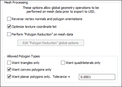
Reverse (flip) vertex normals and polygon orientations
If this option is enabled (checkmarked) then the orientation of all polygons will be reversed, indirectly causing the vertex normals to also face in the opposite direction. For example, if the vertex normals of the object currently all face inward then this function will cause all of the vertex normals to face outward, and cause the orientation of each polygon to flip between clockwise and counter-clockwise.Optimize texture coordinate list
Checkmark this checkbox to have the any duplicated uv texture coordinates removed.Perform "Polygon Reduction" on mesh data
If this checkbox is enabled (check-marked) then the USD exporter will apply the global polygon reduction algorithm to each mesh object just prior to them being embedded in the USD file.The algorithm allows the number of polygons in the scene to be greatly reduced. The parameters used to reduce the polygons can be modified by pressing the "Edit Polygon Reduction Global Options" button. Press the "Help" button on its corresponding dialog box to learn more about the polygon reduction system.
Allowed Polygon Types
These options determine how polygonal mesh geometry will be modified prior to export to the USD file.Want triangles only
Checkmark this checkbox to cause all polygons to be triangulated prior to output.Want quadrilaterals only
Checkmark this checkbox to cause 5 or more sided polygons to become triangulated.Want convex polygons only
Checkmark this checkbox to cause non-convex polygons to become triangulatedWant planar polygons only. Tolerance = #
Checkmark this checkbox to cause non-planar polygons to become triangulated. Normally vertices of each polygon lie in a single plane, but occasionally a polygon could be created for which one or more of its vertices lie above/below its averaged plane. The tolerance value specifies how far a vertex (in object space coordinates) must be away from the polygon's averaged plane for the polygon to be considered non-planar.
This panel controls the output of 3D NURBS curves and 3D spline shapes to the USD file.
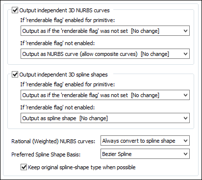
Notes:
- USD supports proper NURBS curves (and trimmed-surfaces) including a separate weights-array. However, it leaves interpolation/representation up to the down-stream "consumer" of the USD data as there is no NURBS tesselation logic inside the USD SDK itself.
- PIXARs USDView does not tesselate/interpolate between CVs for either spline-shapes or NURBS curves. It displays a simplified line-drawing between the CVs.
- Omniverse apparently follows the RenderMan logic, which is to treat curves/splines effectively as "renderable pipes". They combine the curve with a 'width' parameter, and then produce a 3D cylinder/pipe along the curve's path.
- Curves are exported to the 'UsdGeomBasisCurves' Prim which can hold multiple curves with the caveat that all curves share the same interpolation type.
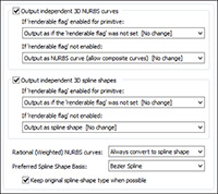
Output independent 3D NURBS curves
The Okino core software has a very extensive NURBS curve sub-system. Each NURBS curve object can have 1 or more NURBS curves associated with it. Multiple curves inside a single object can either be considered to form a single continuous "composite" curve, or each curve can be considered unique, closed, planar (in world space) and oriented such that the curves of the object can be directly converted into a trimmed NURBS surface (in other words, the first curve forms the boundary of the surface and subsequent closed curves form the holes).The following options control how the various NURBS curve configurations can be converted during the export phase.
If 'renderable flag' is enabled in the NURBS curve primitive:
If the Okino 'renderable' flag of a NURBS curve primitive is internally enabled, and the curve(s) form closed loops, then it is possible to convert the NURBS Curve primitive into a renderable closed 3D polygon.
The following options define what will be done to NURBS Curves primitives during the export phase when their 'renderable' flag is enabled:
Output as if the renderable flag was not set [ no change ]
The Okino NURBS curve primitive will be converted into a corresponding USD NURBS curve.Convert and output as polygon mesh
The closed NURBS curve primitive will be converted into a mesh object prior to export.If 'renderable flag' is not enabled:
If the 'renderable' flag of a NURBS Curve primitive is not enabled then the curves will be considered just as plain curves that cannot be seen when rendered. In this case, the following options define what will be done to NURBS curves primitives during the export phase when their 'renderable' flag is disabled:
Output as NURBS Curve (allow composite curves) [ No Change ]
The NURBS Curve primitive will be converted into a corresponding USD NURBS curve. If the source curve has multiple segments then it will be exported as a USD "composite curve.Output as NURBS Curve (single curve only)
The NURBS Curve primitive will be converted into a corresponding USD NURBS curve. If the source curve has multiple segments then it will be exported as a single unified USD NURBS curve.Output independent 3D spline shapes
The Okino core software has an extensive spline primitive sub-system. This primitive accommodates one or more spline curves per primitive. If the multiple spline curves are each closed then the overall Spline Shape is termed "renderable" and can be thus converted into a polygon mesh or a trimmed NURBS surface. For example, the letter "B" can be defined by 3 Bezier curves, the first forming the outer boundary and the latter two forming holes.Note, that unlike the NURBS Curve primitive, each spline curve of the Spline Shape is composed of only a single curve segment (no composite spline curves are allowed).
The following options control how the various Spline Shape configurations can be converted during the export phase. The Spline Shape primitive also handles almost every major spline type (Bezier Spline, B-Spline, Cardinal Spline, Linear Spline, Tensioned Spline, TCB Spline), and their internal cross conversion (between spline types) or between the various spline types and a NURBS curve.
If 'renderable flag' is enabled in the spline shape primitive:
Output as if the renderable flag was not set [ No Change ]
The Spline Shape primitive will be exported as a resampled USD NURBS curve.Convert and output as polygon mesh
The Spline Shape primitive will be converted into a polygon mesh object prior to export.If 'renderable flag' is not enabled:
Convert and Output as NURBS Curve (allow composite curves) [ No Change ]
The Spline Shape primitive will be resampled into a corresponding USD NURBS curve. If the source curve has multiple segments then it will be exported as a USD "composite curve.Convert and Output as NURBS Curve (single curve only)
The Spline Shape primitive will be converted into a corresponding USD NURBS curve. If the source curve has multiple segments then it will be exported as a single unified USD NURBS curve.Rational (Weighted) NURBS Curves:
These options control what is to be done to NURBS curves which have rational/weighted CV values.Always Convert to Spline Shape
Maya and Blenders USD importers presently fail to import the CV point-weight values of NURBS curves. Hence, to circumvent that problem, this defaulted combo box option will resample and convert all such weighted NURBS curves to linear or Bezier spline curves instead.Use Primary NURBS Curve Setting
This option will not treat weighted/rational NURBS curves differently from non-weighted NURBS curves. Such NURBS curves mat not import properly into Maya or Blender.Preferred Spline Shape Basis: Bezier Spline, Linear Spline
This drop-down box determines the type of USD spline curve which will be used if and when an Okino curve needs to be resampled. For the USD exporter, liner and Bezier curve types are supported for resampling.
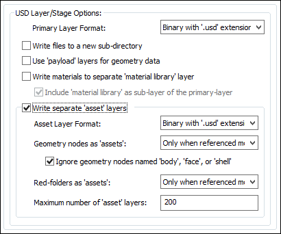
This panel controls the output of layers to the USD file.
A Quick Overview of the USD Layer Concept:
A Layer is a collection of Prims and their Properties that can be saved to/loaded from disk or memory. As such, it can be considered a savable hierarchy.
Layers are a component of the collaborative nature of USD. Each layer in USD signifies a users opinion on assets inside a stage. Layers can override other Layers. A Layer contains zero or more Prims, that in turn describe Property and Metadata values. Each layer possesses an identifier that can be used to construct references to the Layer from other Layers.
USD Layers are represented on disk via USD binary or text-based files. Additionally, Layers can be extended to other 3D file formats by adding in an associated 3D file format plug-in to the USD framework, such as for Wavefront OBJ or FBX.
In some sense this is a bit similar to Okinos red folder mechanism which allows for (1) complex hierarchical grouping folders and associated geometries to be defined but hidden within the virtual red folder, and (2) one or more instances can created and placed into the 3D scene from the red folder definition. For example, the complex make-up of a cars tires and brakes could be placed into an Okino red folder or USD Layer and either of them replicated 4 times without actually needing to replicate the underlying grouping hierarchy and geometry.
As Explained by NVIDIA:
- Layers are probably the single most innovative feature of USD. Conceptually, they have some similarities to layers in Adobe Photoshop: the final composite is the result of combining the effects of all the layers in order. But instead of modifying the pixels of an image like Photoshop layers, USD layers modify the properties of the composed 3D scene. Most importantly, they provide a powerful mechanism for collaboration.
- Different and independent users can modify the composed scene on different layers on each of their own computers, and their edits will be non-destructive. The stronger layer will win out in the composition, but the data from the weaker layer remains accessible. Beyond direct collaboration, the ability that layers provide to non-destructively modify what others have done enables the kind of composability that has made the traditional web so successful.
From Okinos Perspective:
USD Layers are like commonly implemented XRefs -- External File References but on steroids. It is a very clever system but at times a bit too flexible. That flexibility had made the implementation of this high fidelity Okino USD importer challenging as the compositing nature of USD Layers is more of a realtime runtime aspect of using USD and not a static function that this importer can easily simulate or emulate.
Conceptually Layers are basically separate disk-based files. There are complex rules about how Layers can be combined. Each Layer can have an "opinion" on absolutely anything in the (combined) scene graph, so these are somewhat like ultra-flexible XRefs.
In a hypothetical "animation studio pipeline", each department (modelling, shading, rigging and animation) could have its own file/Layer while working in a collaborative manner on a shared 3D scene. So, one hypothetical structure for an asset might look like:
./assets/dragon.usd The base USD file that just pulls together the other layers/files
./assets/dragon.geom.usd Geometry-definition of the "dragon" asset
./assets/dragon.mtl.usd Material-definitions and potentially material-assignments for the "dragon" asset.
./assets/dragon.rig.usd Skeletal animation rig for the "dragon" asset, including vertex-weights, etc.
./assets/dragon.anim.usdd Animation of the "dragon" rig
This scenario could get even more granular but the "recommended approach" is primarily to split the 3D scene/asset so that individual artists would be working on their own files/Layers, and not directly saving over each others' files.
Primary Layer Format: Binary .usd, Binary .usdc, Text .usda
This combo box should be self-explanatory.The "primary layer" is the file selected via the "Save As" dialog. Other layer-files are generated in relation to that location. An explanation of the various USD file format choices can be read on the Main options panel.
Write files to a new sub-directory
Enabling this option will adds a new sub-directory into which the USD files are written.For example, if the file selected for output is "C:\usd_files\myfile.usd", then a sub-directory "C:\usd_files\myfile" will be created, and the primary-layer will be saved out to "C:\usr_files\myfile\myfile.usd".
Use payload layers for geometry data
There is often a lot of stress on utilizing payload USD files, especially when the 3D scene is particularly large and slow to load, for which you could choose not to load in selective payload segments. A payload is basically a file reference that you can choose not to load into the current scene. In the example above, the dragons complex geometry could be hidden inside a nested USD Layer named such as "./assets/dragon.geom.payload.usd".The basic idea is that USD can "hide" geometry inside specialized 'payload' layers. When a down-stream tool supports this, they can process the USD scene without needing to load the payloads geometry. Or, they can selectively load the payload layers one-by-one for processing, rather than needing to be loaded all at once.
As paraphrased from the OpenUSD WEB site, for Packaged assets with Payloads:
When dealing with very large scenes, many important pipeline tasks can be accomplished without knowing about or processing all of the geometry and shading on many (or all!) of the assets in the scene. These tasks can therefore be accomplished much more quickly if we can get a view of the scene that does not populate those aspects of the referenced assets. USD provides a composition arc called a Payload that is essentially a deferred reference. It allows us to structure scenes so that we can open a Stage unloaded, meaning that we USD will populate the stage only up to the payload arcs. One effective way to make use of this is to publish each of your model assets such that the file that gets referenced into assemblies and shots is a very lightweight description of the models interface (e.g. its AssetInfo, VariantSets, rest bounding box), and a payload arc to a separate file that pulls in the complete geometric and shading description of the asset.
When a scene constructed from references to assets built this way is opened unloaded, you get a summary view of the scene that will contain its Model Hierarchy, which is sufficient for some entire tasks, and if not, provides all the information necessary to load just the model instances required for the task. Large scenes can take seconds or minutes to open, but typically the Model Hierarchy view can be opened in under a second, or a small number of seconds.
If this option is enabled then all layers (primary-layer + asset-layers) will have an associated geometry-payload-layer as needed.
Write materials to separate material library layer
Enabling this option will cause all material-definitions to be written to a separate "myfile.materials.usda" layer. This layer file is always 'text' for easier editing. This lets the end-user manually edit the material-definitions, or override texture file-references, etc.Include material library as a sub-layer of the primary layer
When the material-library layer option is not enabled, all material-definitions are internally visible as "".When the material-library layer option is enabled, these are then external-references to "@./myfile.materials.usda@". In order to make the material-library "show up" in the same place, we make the '.materials.usda' a "sub-layer" reference of the primary-layer. This just defines a mapping so that "@./myfile.materials.usda@" and "" will reference the same basic material-definition.
This option should not be disabled in most everyday situations.
Write Separate Asset Layers:
Enabling this option will create separate asset-layers. Its sub-options control how the asset-layers are grouped/selected.Asset Layer Format: Binary .usd, Binary .usdc, Text .usda
This combo box should be self-explanatory but this is the setting for the asset-layer files. An explanation of the various USD file format choices can be read on the Main options panel.The following options determine how the USD exporter best guesses as to what items are to be placed in their own useful asset-layers:
Geometry nodes as new Asset-Layers:
NeverNo geometry items will be considered as new asset-layers.Only when referenced more than once [ Default ]
Only geometry items which are instanced (referenced) more than once in the scene will be considered as new asset-layers. This is the default action.Always
All geometry items will be considered as new asset-layers.Ignore geometry nodes named body, face or shell (data coming from CAD files)
CAD files often have a plethora of geometry items named body, face or shell. Creating a new asset-layer for each aforementioned CAD geometry item would lead to hundreds of files on disk which would become unwieldy and hence should not be done.Red-folders as assets:
Red folders are Okinos equivalence to MCAD Assembly Nodes or Layers from USD. They allow sub-hierarchies to be created and grouped for which the red folder itself can then be instanced 1 or more times into the 3D scene.Never
Only when referenced more than once
AlwaysThese follow the same rules and explanations as described above.Maximum number of asset layers = 200
Having too many asset-layer files on disk can become slow and unwieldy. Hence, this type-in number provides a user-selectable upper value to cap the number of files written to disk.
Materials and texture maps are assigned to mesh objects in USD files via material definitions. This panel controls the output of the material definitions, their associated texture maps, and provide fine grained control over the tweaking and modification of each USD material property.
Notes:
- Material assignments are currently following a PIXAR "USDView-friendly" one-material-per-mesh policy. USDZ (Apple/ARKit) and Omniverse are capable of using "GeomSubset" functionality to assign multiple materials to a single mesh but then PIXARs USDView cannot view/display those materials.
- If an exported scene has its texture maps looking too bright or washed out then enable the "Merge and mix ambient color into diffuse color" checkmark option. Then manually disable or delete the default ambient light inside of USD.
This panel controls the output of layers to the USD file.
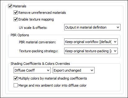
Output Materials
If this checkbox is checkmarked then materials will be exported to the USD file.Remove unreferenced materials
If this checkbox is checkmarked then materials which are not associated with any geometry objects will not be written out to the USD file.If this checkbox is uncheckmarked then every material of the source scene will be written out to the USD file, regardless of whether they are used or not by any geometry objects.
Enable texture mapping
If this checkbox is checkmarked then the following PBR-centric texture maps will be output, depending on the material in question:Ambient Occlusion Base Albedo Displacement Emission Color Glossiness Metalness Normal Map Roughness Specular Color Clearcoat Intensity Clearcoat Roughness Surface OpacityNote that unlike some other formats (including glTF) UsdPreviewSurface does not support a separate normal-map for the clearcoat layer. This can lead to unanticipated downstream results, as any assigned 'clearcoat-normalmap' may be silently ignored on export.
For non-PBR materials, the classic (legacy) Diffuse texture map will be exported as a PBR Albedo map.
UV scale & offsets
Each texture map reference used in an Okino material allows for the texture map to be scaled and offset in "UV space". This combo box determines how this scale and offset information is output to the USD file.Do not output (ignore)
The information is not output. You would normally not want to use this option since the applied textures will look wrong if any of them have scaling or offsetting.Output in material definition
The texture's UV scale and offset values will be written to the USD file using inputs:scale and inputs:translation.Embed in uv coordinates of geometry data
The texture's UV scale and offset values will be multiplied into the uv texture coordinates of each exported mesh geometry object to the USD file.PBR Options
These options control the export of Metallic-Roughness or Specular-Glossiness PBR materials. Okino has an extensively implemented PBR material shading system.PBR Material Conversion
These combo box options determine how Okino PBR material definitions will be exported to a USD PBR material shader.Keep Original Workflow [Default]
The exported material will be output either as a Metallic-Roughness or Specular-Glossiness PBR shading model depending on which variation was used by the original Okino PBR material.Convert to Metallic Workflow
The Okino material will be converted and exported as a Metallic-Roughness shading model.Convert to Specular Workflow
The Okino material will be converted and exported as a Specular-Glossiness shading model.Non-PBR (Legacy/Standard) Material Conversion
These combo box options determine how legacy/standard (non-PBR) Okino material definitions will be converted and exported to a USD PBR material shader. Legacy/standard materials will most often be the common case for data sources from MCAD/CAD files and most 3D file formats other than glTF or USD.Convert to Metallic Workflow (default)
This option maps a subset of the traditional legacy/standard material values over to an approximation of a PBR Metallic-Roughness shading model for the USD file.Convert to Specular Workflow
Likewise, this option maps a subset of the traditional legacy/standard material values over to an approximation of a PBR Specular-Glossiness shading model for the USD file.
Okino Standard Material USD PBR Material Parameter Diffuse texture map Albedo texture map Opacity texture map Opacity texture map Diffuse color Albedo color Luminous color Emissive color Ambient color Ignored Specular colour Converted as a "per-material" setting Opacity (if opacity < 1.0, opacity-mode == Blend; otherwise Mask) Opacity To Metallic-Roughness: Specular color Reflectance Phong shininess (0 to 200) Approximated roughness Note: metalness set to 0.0 To Specular-Glossiness: Specular color Specular-color @ 0.04 specular-intensity. The '0.04' multiplier matches the "metalness == 0.0" concept. Phong shininess (0 to 200) Approximated glossiness Texture-Packing Strategy
PBR related materials are often related to texture packing in which several different grayscale texture channels (such as metallic (R) and smoothness (A)) are packed into a single RGB or RGBA bitmap image for compactness and memory efficiency. The USD format is highly flexible when it comes to texture-packing.Keep Original Texture-Packing [Default]
This option attempts to preserve the incoming texture-packing. So, for example, Unitys "metallic (R) + smoothness (A)" textures will be passed through unchanged.Compatible with glTF Rules
With this option chosen, the texture packing is performed as follows:
- Albedo Color (RGB) + Opacity (Alpha)
- For Metallic-Shininess shading model:
- ARM/ORM: AO (Red), Roughness (Green), Metallic (Blue)
- Reflectance Color (RGB) + Reflectance-Intensity (Alpha)
- For Specular-Glossiness shading model:
- Specular Color (RGB) + Glossiness (Alpha)
Compatible with USDZ Rules
This option effectively eliminates any texture-packing when exporting into USDZ files. For example, an incoming packed "ORM" texture map image from glTF would be split into 3 separate grayscale textures of: occlusion, roughness, + metallic.Shading Coefficient and Colors Overrides
These combo boxes provide hands-on control over how exported material shading parameters should be modified so that the exported model can be rendered nicely as it would have looked in the source 3D program. The two combo boxes and the single numeric text box provide you good control over the ambient and diffuse shading coefficients exported to USD.The first drop-down combo box selects which of these shading parameters is to be modified. Each shading coefficient has its own operation that can be selected (via the second combo box) and an optional numeric text value (via the third data entry text input box). The following describes the various shading parameters that can be controlled:
Ambient Coefficient: This controls the amount of color reflected from an object based on the ambient light in a scene. A good default value is 0.1 through to 0.3 and ideally ranges from 0.0 to 1.0.
Diffuse Coefficient: This controls the amount of color reflected from an object based on the direct light shining on it. A good default value is 0.4 and ideally ranges from 0.0 to 1.0.
Opacity: This is the inverse of transparency. 0.0 will make the object fully transparent, while at 1.0 the object will be fully opaque.
For each material shading parameter, several actions can be performed on each material shading parameter during the import process:
Do Not Export: When this option is selected, the shading parameter is set to 0, effectively making the shading channel appear black (for color channels).
Export Unchanged: When this option is selected, the shading parameter is exported as is, with no change.
Set and Use Default: When this option is selected, the shading parameter is set to some "good" default value (as determined by the export converter). This default value will be displayed in the input text box.
Set to Specific Value: When this option is selected, the exported shading parameter will be overridden with the user specified value of the numeric input text box.
Export and Crop by: When this option is selected, the shading parameter is exported and will remain unchanged if it is less than the numeric text input value shown on the dialog box. If it is greater, then the exported value will be clamped to be no greater than the numeric type-in value. This is a good operation, for example, if you do not wish for the ambient shading coefficient to be greater than 0.3.
Export and Scale by: When this option is selected, the shading parameter is exported and multiplied by the numeric input text value shown on the dialog box
Multiply colors by material shading coefficients
Inside Okino's internal scene graph each material has a "color" and a corresponding "shading coefficient" for each ambient, diffuse and specular color definition. The "shading coefficient" can be considered a variable intensity control that brightens or darkens its corresponding color, without having to modify the color itself.If this checkbox is checkmarked then each shading coefficient is multiplied into its corresponding color value before being exported to the USD file material. Normally you would want this option enabled as it creates a USD material definition which is very close in appearance to an Okino material definition.
If this checkbox is not checkmarked then only the raw colors will be output to the USD file and their corresponding shading coefficient values will be ignored. This will typically result in brighter, bolder and punchier materials, what we ourselves term "OpenGL" shading which tends to be more saturated than colors seen in photo-realistic rendering programs.
Merge and mix ambient color into diffuse color
Enabling this checkbox will cause the materials ambient color to be mixed into the diffuse material color before the final diffuse color is exported. Disabling this checkbox will not output any ambient material color.
This dialog box controls how referenced bitmap texture files will be handled during the USD export process, such as being automatically converted to JPEG or PNG.
Texture Bitmap Handling Method (Combo Box)
This combo box determines the preferred method to output texture bitmap disk references:1] No Bitmap Conversion, No Bitmap Filename Changes
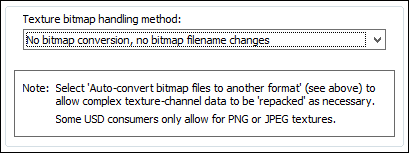
If this combo box option is selected then:
- The texture image will be placed in the USD file as a texture reference.
- The filename and file path to the texture image on disk will not be changed.
- The filename extension on the bitmap reference will not be changed.
- The path to the bitmap will not be changed.
- No automatic bitmap conversion will be performed.
2] Replace File Extension For All Bitmap References
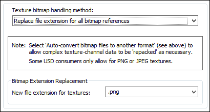
This is similar to option # 1 above, except that:
- The file reference placed in the USD file will be changed such that its file extension is changed to that specified on the dialog box.
For example, if the option is set to PNG then all bitmap filename references will be changed so that their file extensions end in .png
This is a useful option when all of the referenced texture maps have already been converted to this desired file format on disk.
3] Auto-Convert Bitmap Files to Another Format
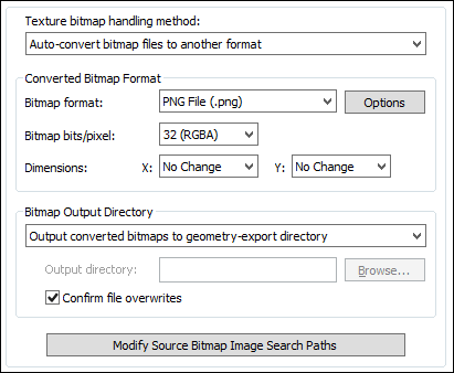
If this combo box option is chosen then all 2D bitmap images that are used by the current scene will be automatically tagged and converted into a new user-specified 2D bitmap file format on the local disk. The bitmap image will be written to the USD file as a file reference and not as an embedded texture image.
For example, if the scene makes references to PNG bitmap files then this option can be selected so that the PNG images are automatically converted to the TIFF format.
If the bitmap texture(s) cannot be found in the location specified by the pathname pre-pended to the texture filename then the USD exporter will search for the texture(s) in all directories specified in the file search paths (these can be modified by pressing the "Modify Source Bitmap Image Search Paths" button).
Converted Bitmap Format
Bitmap File Format (Combo Box)
This combo box lists the desired destination bitmap file format that all texture bitmap images should be converted into.
Bitmap Bits/Pixel: 2, 4, 8, 24 (Combo Box)
This combo lists determine the number of bits/pixel to write out to the new 2d bitmap file. The default is 24 bits. A color quantization algorithm will be used for the 2, 4 and 8 bits/pixel output formats. Not all bitmap file formats can accept 2-8 bits/pixel (e.g. in particular JPEG).
Dimensions: X = #, Y = #
These two drop-down list boxes determine the X and Y resolution for the converted bitmap file(s):
No Change = Do not change the X or Y size Closest = Use the next highest power-of-2 size 2, 4, 8, ... 256, 512 = Choose a specific size for the X or Y dimension Bitmap Output Directory
This combo box determines where the new bitmap file will be written to. Note that enabling the "Replace file paths in all bitmap file references" option or the "Strip file paths from all bitmap references" option from the 'Bitmap Image File Paths Panel' will change the path prefix for the converted bitmap even though it was saved to disk in the location specified by one of these options.
Output Converted Bitmaps To Geometry-Export Directory
The new bitmaps will be written to the directory where the exported files are being written to.
Output Converted Bitmaps To The Specified Directory
The new bitmaps will be written to the directory specified by the input text edit box (labeled as 'Output Directory'). This directory can be changed by pressing the 'Browse' button.
Confirm File Overwrites
If this checkbox is enabled (checkmarked) then the bitmap converter will confirm any potential overwrites of existing bitmap files on disk that have the same filename and extension as the one being written. If this option is disabled then no confirmation will be made.
Modify Source Bitmap Image Search Paths
In specific circumstances it may be necessary to inform the USD exporter where your source bitmap images are located so that automatic bitmap file conversion process or the image embedding process can locate and load the images.
If the USD exporter reports warnings that specific images could not be located during automatic bitmap conversion or embedding, then press this button so that the Search-Paths dialog box appears. Using this dialog box you can inform the USD exporter where the source bitmaps are located.
If a texture bitmap file reference is to be added to a USD file then this panel controls what will be done to the file path of that image filename.
Notes:
- USD texture-/asset-paths are arbitrary UTF-8 strings but they must be resolved by the ArResolver of the USD SDK while loading the USD file.
- The type ArDefaultResolver will treat these asset-path strings as filenames following the usual filename rules for the running OS.
- Specialized asset-resolver plugins can provide access to other URI-based values such as http:// or omni:// but these are not guaranteed to be present.
- The characters [ and ] have special meaning and should be avoided in texture-/asset-paths.
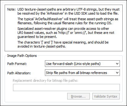
Path Format Combo Box
This combo box determines what kind of file path format will be used.Use back slash (Windows-style paths)
If this option is chosen then all bitmap file paths written to the file will be converted to a Windows/DOS compatible format. In particular, directory separators will be converted to backward slashes \.Use forward slash (Unix-style paths)
If this option is chosen then all bitmap file paths written to the file will be converted to a UNIX compatible format. In particular, all Windows and DOS specific backward slashes \ will be converted to UNIX forward slash / directory separators.Also, any DOS-like drive specifiers, such as c:\ will be removed from the file path and a warning message will be reported indicating of the removal of this drive specifier (it should be ensured that all DOS-like drive specifiers are replaced by UNC specifiers, such as \\machine1\).
Use the RFC 1738 (URL paths)
All bitmap file paths written to the USD file will be converted into the "RFC 1738" URL format specification.Path Alteration
In most 3D graphics programs and file formats a texture map reference is defined as a relative or absolute disk-based directory path which is appended with the name of the bitmap texture map + its file extension, such as c:\files\textures\bitmap.tif. This combo box and its options allow the directory path to be stripped or replaced with something new.No replacement (no change)
If this option is chosen then the file path and texture bitmap image reference will not be changed.Strip file paths from all bitmap references
If this option is chosen then any file path on a bitmap image reference will be stripped off. For example, "C:\polytrans\bitmaps\texture.tif" will be output as "texture.tif".Replace file paths in all bitmap file references
This option allows all exported bitmap references to be prefixed with a new URL file path.For example, if an original texture map references the filename:
c:\files\textures\bitmap.tifand the new URL is specified on this dialog box as this relative-path:
images/then the bitmap filename will be stored in the file as:
images/bitmap.tif
This panel controls the export "animation conversion engine". This engine allows object, camera and light animation data to be exported cleanly and properly to USD.
Okino pioneered the concept of animation cross conversion and hence has a very complex & refined conversion engine which is used all throughout the 3D production market. This conversion process is based on our proprietary Arctic animation processing toolkit. The toolkit is a one stop shop for the handling, cleansing, correcting, processing, re-sampling and cross converting of all variations and types of 3D animation data. The USD exporter sits on top of the Artic toolkit which ensures the accurate export of USD animated entities. Ditto for the animation support in our USD importer.
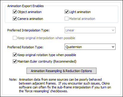
Object Animation
If this option is enabled (checkmarked) then object animation data which is currently contained within the internal database will be exported.Camera Animation
If this option is enabled (checkmarked) then camera animation data which is currently contained within the internal database will be exported.If this checkbox is grayed out (disabled) then you will first need to enable the Output Cameras checkbox on the Selective Output Options Panel # 2.
Light Animation
If this option is enabled (checkmarked) then light animation data which is currently contained within the internal database will be exported.If this checkbox is grayed out (disabled) then you will first need to enable the Output Lights checkbox on the Light Output Options Panel.
Preferred Interpolation Type: Linear
This combo box determines which type of keyframe interpolation method should be used for the exported USD file. Unfortunately USD is limited to step or linear interpolation only.Preferred Rotation Type (Quaternion, Euler XYZ, XZY, YXZ, YZX, ZXY, ZYX)
When we refer to the "rotation controller type" (or just rotation type), we are indicating whether a rotation animation is expressed in terms of Quaternions or in terms of Euler Angles. When rotation data is expressed in terms of Euler Angles, it is expressed in terms of some specific rotation axis order (such as XYZ or YZX). The rotation controller type of the original source animation data will have been chosen by the format-specific importer which brought the source data into Okinos software. Generally, the rotation controller type of the original source animation data could vary from object to object, from camera to camera, and from light to light.If and when animation resampling occurs on a rotation channel, the resampling process must select a target rotation type. Since repetitive-order Euler rotations (XYX, ZXZ, etc) of the source animation data are not entirely compatible with USDs repetitive-order Euler rotations, it is sometimes necessary to pick an arbitrary rotation type as output for the resampling process. This arbitrary choice is left in your hands and is selected via this drop-down box.
Whenever the original rotation type can be replicated into USD you have a choice between keeping the original rotation type or always using one specific rotation type. That choice is controlled by the "Keep Original Rotation Controller Type When Possible" option below. If you disable that checkbox, then all rotation animation exported to USD will be forced to use the rotation type selected in the "Preferred Rotation Type" list box.
Keep Original Rotation Controller Type When Possible
If this checkbox is enabled then the resampling process will attempt to preserve the rotation controller type used in the original source animation data. This can often be accomplished, but not in all cases. When it can be accomplished, then the rotation animation exported to USD will use the same rotation controller type as the original source animation data. Otherwise, the rotation animation exported to USD will use the "Preferred Rotation Type" as specified above. You will typically want to keep this checkbox enabled, unless you have specific reasons for wanting all your USD rotation animations to use the same rotation type.NOTE: When this checkbox is enabled, rotation keyframe resampling might still occur. However, the resampled rotation keyframes will have the same rotation type as the original source animation data, when possible (or the "Preferred Rotation Type" when the original source animation data's rotation type is not compatible with USD).
NOTE: The rotation type is not to be confused with the interpolation type. The selection of rotation type determines which rotation data channels are created for USD (either a single Quaternion channel or 3 independent Euler Angle channels), as well as which Euler Angle order to use (when the rotation type is not Quaternion).
If this checkbox is disabled then the resampling process will use the "Preferred Rotation Method" you have specified above. If the original animation source data has a different rotation type, then resampling must occur. If the original source data has the same interpolation type as the "Preferred Rotation Method" you have specified above, then resampling will only occur if otherwise mandated.
Maintain Euler Continuity (Fix up -180/180 Degree Euler Flips)
This option fixes exported Euler rotation channels which flip back and forth between values close to 180 degrees and -180.0 degrees, from key to key. Normally this flipping will not pose a problem unless USD "slows down" an animation for previewing in slow motion, and does sub-key interpolation (in such cases the objects may appear to randomly spin in the wrong direction at specific keys).This option can only take effect when rotation curves are explicitly resampled during the import process.
NOTE: This option will not take effect if the 'Preferred Rotation Type' is set to Quaternion and the 'Keep Original Rotation Controller Type When Possible' is disabled.
Background Info:
There are several cases where the exported rotation animation needs to be "resampled" from one mathematical format to another, such as if the Euler order has to be changed, or when quaternion animation needs to be cross converted to Euler animation curves for USD.The resampling process first converts the rotation value(s) at each keyframe to a 4x4 rotation matrix, and then the matrix is decomposed into explicit (X, Y, Z) Euler rotation angles, of the desired Euler order. The Euler angles will always be in the range -180 to 180 degrees.
The primary disadvantage of the traditional Euler decomposition method comes about when the target program tries to view the animation in a "slow motion" mode. Since two adjacent frames might have values of, say, -179.9 and 179.9 (or vice versa) on one of the Euler angles, the sub-frame interpolation between these values will result in a quick spin through 359.8(!) degrees, rather than the intended 0.2 degree change. When a "slow motion" mode is not in effect, the user will traditionally never see the sub-frame interpolated values because the -179.9 and 179.9 rotations are absolute and correct values (needing no further interpolation between them).
Problem example: if the imported source rotations are 150.0 deg, 179.0, deg, 185.0 deg, 190.0 deg then after resampling the rotations will be 150.0 deg, 179.0 def, -175.0 deg, -170.0 deg. These are correct. However, some 3D viewers, during slow-motion playback where sub-frame interpolation is performed, will look at the 179.0 to -175.0 degree interval and create new interpolated values through a 354 degree rotation interval and not the shorter 6 degree rotation.
What This Option Does:
Enabling this option will allow an additional algorithm to be used which detects cases of "-180/180 degree Euler Flips" and attempts to fix them. This alternative algorithm will take the previous frame of animation into account when performing rotation resampling. It will attempt to decompose the rotation into a equivalent set of Euler angles which represents the smallest Euler-space change of values. This makes the algorithm very good for preventing -180/180 discontinuities in the Euler animation curves. This allows "slow motion" sub-frame interpolation to function as ideally expected.One possible down-side to this alternative algorithm is that Euler angles are free to "drift" away from the normal -180/180 range. Let us suppose you have an animation of a spinning top. Under the traditional algorithm, the top might spin from 0 to 180, then a discontinuity effect occurs, causing the next frames to go from -180 to 0 to 180, and so forth. With this option enabled, the top would spin from 0 to 180, then from 180 to 360 to 540, and so forth. There are hypothetical scenarios where users might not want that to happen. If that is the case, disable this option to ensure that all angles are clamped to the -180/180 range.
Animation Resampling and Reduction Options
Pressing this button will show the animation resampling and reduction options dialog box. This, in general, controls the precision and reduction options used globally during animation resampling (for both import and export). If you find that your exported animation data looks jittery or does not hit target translations/rotations, then reduce the tolerance values.If you disable keyframe reduction, then resampled animation data will have a key at every frame. You might have a specific reason to desire that output. Leaving keyframe reduction enabled, but setting the tolerance values to zero, will result in a curve which perfectly fits the original curve at all frames, but has all redundant keys eliminated. For example, if a channel is actually non-animated, then leaving keyframe reduction enabled with a zero tolerance will result in far fewer keys than entirely disabling keyframe reduction.