

| You are here: Home » Specialized Sections » How To: CAD to STL Conversions |
Support: 905-672-9328 Copyright © 2026 Okino Toronto, Ontario, Canada. |
|
STL is one of the industry's oldest (and simplest) 3D file formats created back in 1987 for 3D Systems' first commercial 3D printer. It is widely used for rapid prototyping, 3D printing and CAM. Okino has provided one of the very first and still primary STL export conversion systems for close to 3 decades.
Please take note that there is no 3D file format which is much simpler than STL. It is not a high-end, high fidelity 3D conversion file format as many people have come to wrongly believe. Rather, STL defines just a raw triangulated polygon mesh with no smoothing information (vertex normals), no uv texture coordinates, no assembly hierarchy part naming or any material assignments. 3MF and VRML2 are often much better file formats for moving 3D datasets into downstream programs and/or 3D printers.
This export converter writes out 3D scenes to an ASCII or binary formatted 'StereoLithography STL' file which can be read by many CAD/CAM and 3D printer related software packages. The following example shows how a single triangle polygon is defined within an ASCII STL file.
solid test facet normal 0 1 0 outer loop vertex 0 4 0 vertex 0.517638 3.93185 0 vertex 0.5 3.93185 -0.133975 endloop endfacet endsolid test
Basic Rules for CAD to STL
1) Always source your CAD files as "BREP solids" geometry items.
2) Set the appropriate 'mesh tessellation' tolerances on the CAD importer.
2b) Import the CAD model with the Okino 'CAD Optimizer' enabled by default.
3) Upon import check that there are no 'naked' edges in the model.
4) Export to STL.
A fundamental concept to understand for this tutorial is that each geometrical 'part' in a CAD/MCAD model is defined as a solid "body" of which the body itself is defined as one or more geometrical "faces". A 'face' is not to be confused with a mesh triangle or quad polygon but rather a 'face' is an underlying NURBS-based piece of geometry. For the sake of STL export we wish for all the faces within the body to share edges with each other so that the body is considered to be 'water tight'.
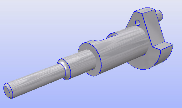
For example, the isolated crank shaft of our engine model is imported as 28 distinct 'faces' rather than one solid body (the latter of which we desire). This is shown in the following screen snapshot whereby the blue edges denote 'naked edges' which are not shared across adjacent faces (and hence this model is presently not necessarily 'water tight' for STL output).
As a contrived example, we will examine a worst case scenario whereby an imported CAD file is not water tight (non-manifold). In the older days this was more common when CAD files were sourced as "Surfaced NURBS" rather than proper, modern "BREP solids" geometry. A good overview about this new-school vs. old-school method of sourcing such CAD files is succinctly outlined herein.
Rule # 1 - Source your CAD files as 'BREP Solids' Geometry
When requesting CAD files from your vendor please have them export the files as 'BREP Solids' and not old-school 'Surfaced NURBS' or 'Bounded Surfaces'. The BREP topology information in such files will be needed to ensure that all the 'bodies' in the CAD file remain water tight.Rule # 2 - Choose an appropriate mesh 'tessellation tolerance' on the CAD importer
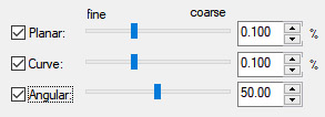
CAD/MCAD models are defined as analytic (numerical) NURBS surfaces which need to be converted into a polygonal mesh. This process is called "mesh tessellation". The number of polygons (or fineness/quality) of the resulting mesh approximation is controlled by 1 to 3 numerical sliders on most Okino CAD importers. In general the default values should suffice. Increasing the tolerance slides will generate more polygons and hence lead to a higher quality model (especially around holes and highly curved surfaces).
For the sake of this tutorial we will be blindly sourcing and importing an engine model from Solid Edge without any knowledge as to whether it was created or exported as 'BREP solids' or old-school 'Surfaced NURBS'.
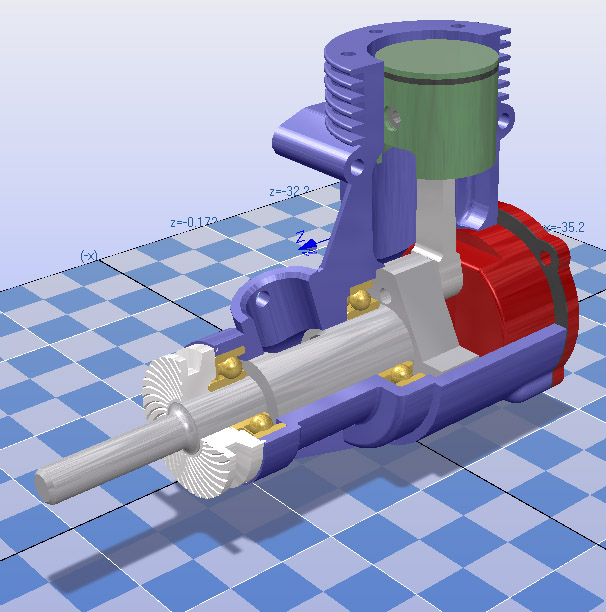
After import the model will be displayed in Okino software as follows:
Rule # 3 - Ensure that the import CAD model is water tight (no 'naked edges', 'manifold')
Statistically, almost all CAD/MCAD models which Okino customers import (in modern times) will be 'manifold' and 'water tight'. But let's review the model visually and find out whether that is the case. This can be done via the 'Edge Analysis' functionality within Okino software. To enable it, choose from the 'Views / Show / Edge statistics window...' menu option.
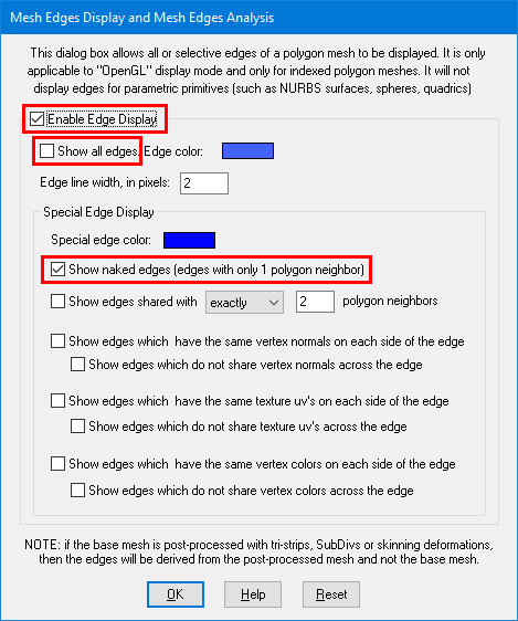
Now press the "Setup Edge Display" button after which you will want to enable the "Enable Edge Display" and "Show naked edges" checkboxes then disable the "Show all edges" checkbox:
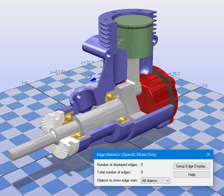
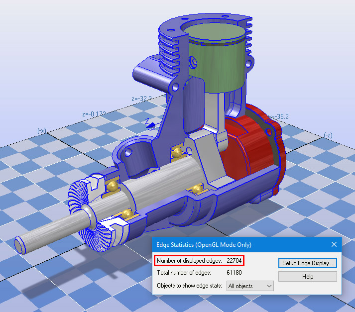
According to the statistics shown in the following image, the engine has 22704 naked edges out of a total of 61180 edges. In other words, this model does not have all edges shared amongst the faces of each geometry body.
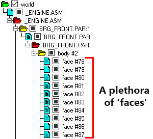
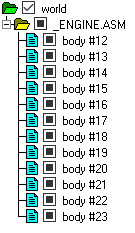
Another tell-tale sign that a CAD model was imported as a disparate set of 'faces', and not a unified set of 'bodies', is to review the CAD assembly hierarchy in the Okino "Selector Window" (located on the right side of the Okino stand-alone software's UI). This is clearly seen in the following screen snapshot for this engine model for which the "body #2" grouping folder has a plethora of disjointed 'face' geometry items. Rather, what we ultimately want is for all of these 'face' geometry items to be collapsed into single "body" objects.
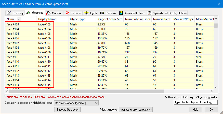
Another handy way to review an imported model is via the Okino spreadsheet editor which can do "almost anything" with an imported model. For this example we won't be using it to reduce or help optimize a model. Nevertheless, you can display the editor by pressing Control-E on the keyboard and reviewing all the objects defined in the model in a linear manner. In the following screen snapshot you can see all the name references to "faces", which is an instant give-away that the CAD model is not necessarily manifold:
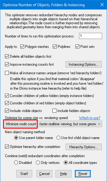
Such automated collapsing of the CAD assembly hierarchy can be done by the most important function in Okino software which is our "CAD part and hierarchy optimizer". This optimizer is enabled by default on all Okino CAD importers but for this contrived example we'll be running it manually on the non-ideal imported CAD model. This is executed from the "Win / Optimize Scene" menu item of the Selector Window. Make sure that the "Minimize node count" combo box is chosen (which is the default):
After execution of the optimizer, the messy hierarchy of disjointed 'faces' will have been collapsed into 12 bodies. The edge statistics modeless window will now show that the number of "Displayed edges" is 0, meaning that all edges in the model are shared (which is our ultimate goal):
Now that the model is ready for output to a 3D printer you can export it to STL using all default options.
The contrived example outlined in the previous section is rather rare in these modern times as most CAD/MCAD models sourced by Okino customers are statistically manifold to start with. And, since the Okino "CAD part and hierarchy optimizer" is enabled by default during all CAD file imports, such imported data should be manifold to start with.
However, some users may not receive their 3D models from a CAD data source. Rather, they may import generic 3D models from FBX, COLLADA, 3ds, OBJ, DXF, STL or many generic and common non-CAD file formats. In such cases it is generally not guaranteed that the edges and vertices will be shared (manifold, water tight).
Without getting into a deeper technical discussion, Okino software has core 'model cleanup' functionality to deal with such general situations in a fairly automated manner.
You will first want to visually review the model using the "Edge Analysis" method explained in the previous section. If the modeless window shows more than zero "Number of displayed edges" then the model is not necessarily manifold. In such cases right click on the top "world" grouping folder in the Selector Window and choose the "Polygon Processing Operations" menu item which will display the following dialog box:
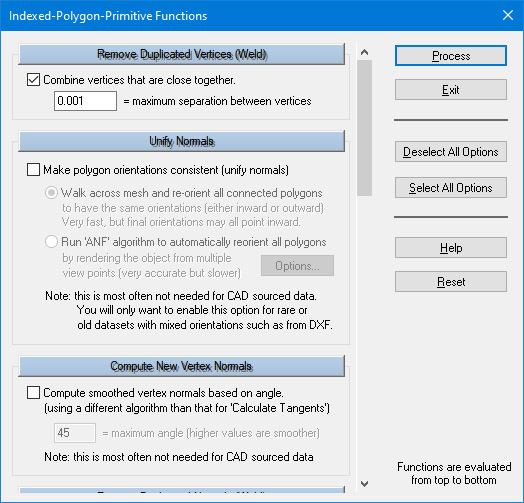
You will want to disable all the options except for "Combine vertices" and "Combine Duplicated Vertex Normals". Press "Process" to start the model clean-up. Afterwards the number of displayed edges should be reduced in number and/or reduced to zero. What this has done is to collapse all vertices which are close to each other into single vertices. This in turn leads to the edges of the triangle polygon mesh being shared (in theory and hopefully in practice).
See also the corresponding STL import converter.
The following information explains the various options on the dialog box:
Output Only 1 'Solid' Entity
If this option is enabled (checkmarked) then each object defined within the database will be output as a separate object in the STL file (enclosed within its own 'solid' definition). If this option is disabled then all objects within the database will be compressed into a single entity before being output to the STL file as a single 'solid' definition.Binary Output
If this option is enabled (checkmarked) then the STL file will be written in binary, else it will be written in ASCII format.NOTE: the binary file format does not allow more than one 'solid' to be defined so this export converter compresses all of the objects defined within the 3d database into a single object before outputting them to the binary STL file (this is equivalent to enabling the 'Output Only 1 Solid Entity' option. This does not apply for the ASCI I mode which allows one or more 'solid' definitions to be created.
Reverse Orientation of Triangles
If this option is enabled (checkmarked) then the orientation of all triangles will be reversed (this will effectively swap the orientation of the triangles' geometric normals). This option will not flip the orientation of the vertex normals.Flip Geometric Normals
If this option is enabled (checkmarked) then the orientation of each geometric normal will be reversed. You may need to enable this option if the STL file looks 'dark' in the final destination rendering program.Line Terminator Type
This common option selects which line terminator is to be used for the ASCII output file:
- Files destined for DOS/PC machines should use CR/LF,
- Files for UNIX machines should use LF, and
- Files for Macintosh machines should use CR.
The default is specific to which machine this converter is presently running on: CRLF for DOS/PC, LF for UNIX and CR for Macintosh. This option normally does not have to be specified unless you will be using the exported ASCII file on a different type of computer.