| You are here: Home » Import CAD Formats » NGRAIN's 3KO Solutions |
|
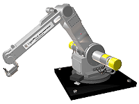
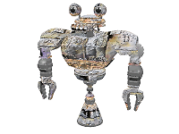
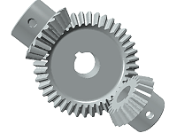
Click on any image below to jump to the scene demos WEB page:
This PolyTrans export converter outputs clean files to the Viewpoint "VET" 3D streaming file format (VET = Viewpoint Experience Technology). This file format was also previously known as Metastream 3 (MTS3). Over a year of development by Okino staff has lead to a high quality and robust VET exporter with dozens of options and many built-in features which will create dependable VET models (such as auto-scaling of the scene, automatic texture map resizing for minimal .mts file size, and much more). You can use the exported VET models immediately within your WEB pages or load them into Viewpoint's "Scene Builder" application for further material editing (such as applying custom light or texture maps).
VET is a popular 3D file format used to stream 3D data across a network, in particular the Internet. A key benefit of VET is its ability to download low resolution models initially, then dynamically increase the resolution of the model over a period of time by sending more polygon vertex information. This exporter was developed over a long period of 11 months at Okino, with close developer relations with the Viewpoint VET development team; it ties in very closely to the Viewpoint VET SDK and utilizes many features/tweaks in order to convert any form of 3D data into the Viewpoint VET format (.mts data files and .mtx scene files) for proper and optimized rendering in a Viewpoint VET viewer.
Quality Publish Enables
Materials Animation
Viewpoint VET is of the new generation of 3D file formats that allow complex and visually rich 3D scene data to be streamed quickly across the Internet for interactive, high quality viewing on WEB pages, or in any Viewpoint VET compatible viewer. The key aspect to the file format is its use of adaptive data compression of the 3D mesh geometry and of the texture maps embedded with the data stream. For slow connections, a basic low resolution image is streamed first and then more complexity is added to the scene as additional vertex information is sent to the destination viewing program. In addition, the use of texturing, light maps and accumulation-buffer type of anti- aliasing leads to final rendered images that look photo-realistic, although rendering times are at interactive viewing rates.
Examples output from Okino's PolyTrans can be viewed by clicking here.
- The ability to stream high quality 3D scenes across the Internet, without
any need for a special streaming server. Depending on 'net bandwidth,
Viewpoint VET can stream either the entire high resolution model at once, or it
can stream out a low resolution model initially and "increase the resolution" of
the 3D model on the client computer by streaming out additional vertex
information in a progressive manner.
- Complex 3D models, such as cars, watches and rings can be represented
with a small amount of data (10k to 60k for some classic Viewpoint VET examples).
- End-users have been given good control over the viewing and orientation of
Viewpoint VET models displayed on a WEB page. Photo-realistic images of models (cars, watches, rings, etc.)
can be interactively displayed on an e-Commerce WEB page providing a buying
experience equal to, or better than that of seeing the items in a real store.
As an example, a computer system can be rotated interactively, and zoomed-in
for close inspection, or animations triggered (such as the CDROM tray
opening or the top of a laptop computer opening up). In a real
store it would probably be much more difficult to flip a computer upside down
to examine the labels on the bottom of the computer monitor. This all leads to
a new online experience for e-Commerce shoppers.
- For business-to-business (instead of eCommerce business-to-consumer),
Okino's PolyTrans can be used to place 3D content data online for other
business users to view. For example, Okino's PolyTrans can convert any
CAD, 3D multi-media or VisSim data for fast, interactive viewing on
the WEB. This is ideal for intranets, or in general any WEB site where 3D
data content is to be displayed photo-realistically, interactively and quickly.
- No need for end-users to download and install a special plug-in module.
According to Viewpoint Corp., only a very small plugin is needed to view
Viewpoint VET data on the end-user's machine and it is automatically downloaded
as required.
- The Viewpoint VET plug-in installed on the end-user's computer is modular in approach. This means that new components can be added, or older components replaced, without having to download and install upgrades. This is all done transparently to the end-user. Since the updates are typically small, the end-user will not notice that they are being downloaded and installed.
- Output of clean mesh data with optional vertex normals and vertex texture
coordinates.
- Embedding of any form of texture image inside a Viewpoint VET file.
- Automatic resizing of texture maps so that they are always a power-of-two
in size.
- Material parameter output: ambient color, diffuse color, specular color,
emissive color, shininess and transparency.
- Diffuse and bump map texture layer output.
- The proper and integrated use of Viewpoint VET instancing so that multiple
instances can share a single geometry (mesh) definition. This can greatly
reduce the size of a Viewpoint VET .mts file if there are many instances which
share the same basic geometry.
- Hierarchy for geometry and folders ("null nodes" or "empty
instances/objects").
- Export of object and camera animation data (version dependent).
- A wide variety of export options that provide good control over the exported Viewpoint VET scene.
In order to achieve high performance and fast interactive rendering rates, the Viewpoint VET viewer seems to work best when scenes/models are roughly the size of a unit cube of 1x1x1 units and with the camera about 4 units away from the model. Black character lines and/or hidden surface problems may occur if the scene is much larger or smaller than this unit cube. To overcome these potential rendering problems the developers at Okino have added some interesting options to this Viewpoint VET exporter:
- If the objects appear too small in the Viewpoint VET viewer (and you have "Output Cameras" enabled and "Output Accurate Camera "Field of View" disabled, which are the best default options) then there is only one ideal method to change this situation: go back to your source 3D program, change the camera's field-of-view to about 35 to 40 degrees, then move the camera's look-from location so that it is relatively close to the objects in the scene. Re-export. Iterate until the VET scene looks good by moving the camera closer/further away from the objects and re-exporting. The reason you have to do this is because the VET renderer was designed to have a camera field-of-view around 35 to 40 degrees and have the camera quite close to your objects. There is no automatic way to set the camera's field-of-view in this exporter unless you enable the Output Accurate Camera "Field of View" option, but in general enabling this option will lead to rendering problems in the VET viewer due to its field-of-view restrictions.
- If shading looks bad, due to incorrect vertex normals (smoothing) then increase the "Geometry Compression Quality" slider from 0.8 to a higher number, such as 1.6. This will provide more geometry to the VET renderer and hence more vertex normals to better approximate the original model.
- If black lines appear when manipulating a model in a Viewpoint VET viewer then reduce the "Edge Bias" slider to a value less than 1.0 until the problem goes away. This is often needed if the mesh has a dense number of polygons (often from CAD data). Lower edge bias values will make the Viewpoint VET renderer more aware of this condition.
- Keep the "Scale Geometry To be No Larger" combo box set to the "2x2x2" option. This will automatically rescale the scene so that it is no larger than 2x2x2 units. We have found that this is a good size to rescale the scene. Viewpoint recommends that the size of the scene be no larger than 2.75x2x2 units.
- If your texture maps appear "noisy" or of low quality inside the Viewpoint VET viewer, then set the "Image Compression Quality" slider higher, close to 100.
- If the shadows below objects appear to bounce "up and down" when the objects are being animated then disable the "Automatic Shadow Height Placement" option and set the shadow height location manually. This problem is due to the fact that the VET renderer recomputes the shadow height location based on the objects' minimum bounding box height value, on a per frame basis.
- Viewpoint recommends that texture maps be no larger than 1024 x 1024 in size. Because textures add to the final .mts file size we recommend that the textures be resized to something smaller using this export converter's option dialog box (128 or 256 should be acceptable).
In order to achieve fast data transfer of 3D geometry across a network, and to achieve fast interactive rendering rates, the Viewpoint VET 3D file format had to assume some limitations:
- The geometry format is "lossy", meaning that some of the quality of the original 3D model is lost in the conversion process. The degree of loss is controlled in this exporter by the "Geometry Compression Quality" slider. It is up to the Viewpoint VET technology to actually perform the geometry compression algorithm itself.
- All geometry will be output as triangles to the Viewpoint VET compression algorithm, as required by the Viewpoint VET file format.
- There are no sense of real lights in the Viewpoint VET file format. All lighting in a Viewpoint VET rendering process is done though "light maps" which are a form of environment mapping. Thus, any lights you set up in the source program will not have any relation to the final exported Viewpoint VET 3D file.
- At the time of this writing, texture maps always tile across mesh surfaces. In other words, texture tiling (texture wrap around) cannot be disabled or selectively turned off in the Viewpoint VET file format. For example, if you have scaled and offset a texture map to apply it as a small decal in the middle of an object, you may very well find that the texture repeats multiple times across the mesh object in the final rendering view. This is a basic limitation of the Viewpoint VET rendering technology.
- Meshes with dense sets of polygons can lead to rendering artifacts, whereby thick black lines appear in the final rendering. This problem can be cured by reducing the "Edge Bias" slider values.
- Scenes that are too large can cause z-buffer rendering problems, in particular hidden surface anomalies. The best solution is to have this exporter automatically rescale the exported scene smaller.
- Names exported to the .mtx file format cannot have '.' periods in them. These are replaced with underscores during the export process.
The "Quality" panel contains some of the most important options, the options which control the quality of the exported data and ultimately the visual accuracy of the data when rendered in a Viewpoint VET viewer.
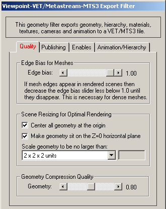
Edge Bias for Meshes
This slider should only be modified if you see thick black lines in the final Viewpoint VET renderings. These lines will often appear for dense polygon meshes, such as from CAD software packages. To fix these rendering problems reduce this slider value less than 1.0 (say, to 0.8). Continue to tweak this value until the problem goes away (this can be done interactively in the Viewpoint VET Scene Builder program). If you set this slider to 1.0 then Viewpoint VET will use its default internal best-guess edge bias.Scene Resizing for Optimal Rendering
From experience, Viewpoint VET scenes render with the least anomalies when the size is roughly the size of a unit cube (1x1x1 up to 2x2x2 units). By enabling the following options (which is the default) all imported data will be resized properly before being exported to the Viewpoint VET file format.Center All Geometry At the Origin
If this checkbox is enabled (checkmarked) then all the geometry data will be positioned so that it is centered about the origin. If disabled then the geometry will not be repositioned. The default is enabled.Make Geometry Sit on the Z=0 Horizontal Plane
If this checkbox is enabled (checkmarked) then the geometry will be repositioned so that it is sitting flush with the top of the Z plane (the horizontal plane). The default is enabled.Scale Geometry to be no Large Than...
This option allows the geometry data to be automatically rescaled if it is too large. If set to 'Do not scale the geometry' then no scaling will be done. If set to '1x1x1 units' then all the objects will be scaled smaller should they exceed 1x1x1 units in total size. Likewise for the '2x2x2 units' option. If set to 'User defined maximum size' then the maximum size of all the objects can be set using the type-in numeric box. The default is '2x2x2 units'.Although not quite the same, if the option is set to Use Absolute Scaling Factor then all objects exported to the MTS3 file will be scaled absolutely by the user specified value. Thus, if you set the type-in value to 0.25 then all objects will be made 4 times smaller and if the value if set to 4 then all objects will be scaled 4 times larger. This is useful is you are converting a variety of different models to MTS3 format and you want them all uniformly scaled with the same scaling factor.
Geometry Compression Quality
Viewpoint VET files achieve their small size by applying a compression algorithm to the mesh data. This slider specifies how much compression should be done on the data. The slider range is 0.0 to 1.6, with 0.8 as the default. Higher values (closer to 1.6) will result in larger files and less data compression.
The "Publishing" panel contains options that control how the exported .mts and .mtx files are created by the Viewpoint VET technology utilized by this exporter.
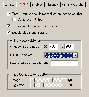
Output .mtx Scene File (as well as a .mts geometry file)
There are two important files exported by this converter. The first is a .mts file which is a binary file containing the compressed geometry and texture maps. The second is a .mtx file (or .mtz file if compressed) which is an ASCII XML-style file containing all the information about the scene, including global scene options, instance hierarchy, camera data and all animation data. If this check box is disabled then no .mtx file will be output.If you wish to have the .mtx scene file compressed, then enable the "Compress .mtx File" option. It will output the .mtx file with the new extension .mtz.
Use Wavelet Compression for Images
If this option is enabled then all texture images will be compressed with the Wavelet compression method when they are stored in the .mts file, else JPEG compression will be used.Enable Global Anti-Aliasing
If this option is enabled then the Viewpoint VET renderer will perform anti- aliasing by rendering the scene multiple times and compositing the various images together to form a nice anti-aliased image.HTML Page Publisher
These options control the automatic creation of an HTML page whose content will load up the .mts/.mtx file in the context of a pre-specified template file.A pre-defined template must be chosen from the drop-down combo box. If you do not wish to have the HTML file generated then select the "[Don't Output Any]" option. The templates are stored on disk in the "vcplugin\vetsdk\templates" directory where the main PolyTrans/NuGraf software resides on disk.
The size of the VET display window on the HTML page is controlled by the "Window Size (pixels)", which defaults to 400x300 pixels.
Image Compression Quality: Image Maps and Light Maps
These two sliders control the amount of compression applied to texture image maps and light maps. Texture image maps are those textures applied to objects. Light maps are the image maps used to approximate light effects in Viewpoint VET renderings. Setting these values to 100 will results in no compression, while lower values will increase the amount of compression (and thus reduce the size of the exported .mts files).
The "Enables" panel control what content is sent to the .mts and .mtx files, in particular the meshes and camera data.
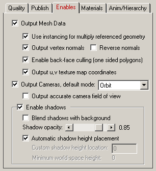
Output Mesh Data
If this checkbox is enabled (checkmarked, which is the default) then the raw mesh data will be output to the MTS3 file along with the following optional attributes:Use Instancing for Multiply Referenced Geometry
An interesting aspect of this export converter is its ability to use the concept of instancing to reduce the size of the exported data files. If multiple instances reference one geometric mesh object, then this exporter will properly output only a single mesh object to the .mts file but have it virtually referenced multiple times in the .mtx file. If this option is disabled then one explicit copy of the geometric mesh data will be output to the .mts file, one for each and every instance; this will produce much larger files with no real benefit.Output Vertex Normals
This option outputs normals and normal indices for all the polygon data. If you do not choose this option, no normal data will be exported. This option is enabled by default.Reverse Normals
This option allows you to reverse the vertex normals of each polygon. If you are finding that some objects appear "inside out" (in other words, the back- face culling is happening for the wrong faces), then enable this option.Enable Back-Face Culling (one sided polygons)
This is a Viewpoint VET runtime renderer option. If this option is enabled then those polygons facing away from the camera will not be rendered. This is called "back face culling" and is used to speed up the rendering process. In many cases this option will be ideal to enable, but in other cases it will make certain aspects of your exported scene disappear that you otherwise don't want to (such as meshes for which the front-facing and back-facing polygons can easily be seen from the camera view).You may also find that the Viewpoint VET viewer culls away polygons that you would otherwise consider to be front-facing, and should not be touched. This can occur due to the orientation of the polygons from the source 3D file format. In general, all polygons must be in a "counter clockwise" orientation when exported to the Viewpoint VET file format in order to be properly considered in the back-face culling operation. If you want to globally reverse the orientation of every polygon in the scene, then enable the "Reverse normals" option.
Output u,v Texture Map Coordinates
If this option is enabled (checkmarked) then (u,v) texture mapping coordinates will be output to the MTS3 file for those primitives which reference 2d textures. If disabled (uncheckmarked) then no texture mapping coordinates will be output. These texture coordinates define how a 2d bitmap image is to be mapped onto the 3d geometric primitive.NOTE: As of the time of this writing, texture tiling (texture wrap around) cannot be disabled in exported MTS3 files. This is a limitation of the MTS3 rendering technology and not of this exporter. Thus, if you place a small decal on an object then you may find that the decal tiles itself across the object many times.
Output Cameras, and default mode
If this option is enabled (checkmarked) then a perspective camera definition will be output to the MTS3 scene file. Four types of camera modes can be selected:
- Orbit: the camera orbits around the model at a fixed look-at location.
- Walk: the camera moves throughout the scene.
- Panoramic: the camera remains static, but the look-at location can be panned around on a tripod.
- Static: the camera does not move at all.
Output Accurate Camera "Field of View"
If this option is enabled (checkmarked) then this exporter will output the field-of-view parameter for each camera so that the angle of view seen in the VET renderer will be equivalent to the source 3D scene.NOTE: this option is disabled by default because the VET renderer most often displays bad rendering artifacts when this option is enabled. In order to display the proper field-of-view in Viewpoint VET the camera's image plane must be scaled up/down in size. However, the VET renderer (in general) only seems to produce good results when the image plane is not scaled. If you encounter rendering problems when this option is enabled then disable it.
Enable Shadows
If this option is enabled then a shadow will appear on the ground plane beneath all objects in the scene. The opacity of the shadow is controlled by the slider (values near 1.0 will make the shadow completely opaque). If the "Blend Shadows With Background" option is enabled then any background image will be properly blended with the shadow depending on the opacity of the shadow.Automatic Shadow Height Placement
If this option is enabled then the Viewpoint VET renderer will automatically place a shadow directly under the bottom-most object's bounding box in the scene. This is ok for static scenes, but if the bottom-most object is animated then you will most likely find that the shadow "bounces up and down" as the object animates; this is because the object's bounding box is moving and thus the shadow is moved as the bottom-most value of the object's bounding box changes.If you find that shadows bounce up and down in animations then disable this option and enter a new value for the shadow's Y (height) location in the "Custom shadow height location" type-in box. This will prevent the Viewpoint VET renderer from setting the shadow's height location automatically. To help you determine an idea value for this type-in box, the text line "Minimum world-space height" will indicate the absolute lowest world-space Y (height) coordinate in the current scene being exported. For example, if the "Minimum world-space height" text is set to -4.5, and you want the shadow about 2 world-space units lower than the lowest object, then set the "Custom shadow height location" type-in box to -6.5 (-4.5 - 2.0 = -6.5).
The "Materials" panel control the output of materials and textures to the .mts file.
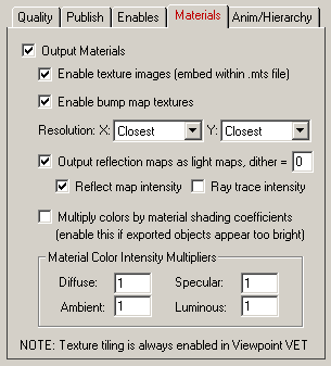
Output Materials
If this option is enabled (checkmarked) then materials and their related parameters will be output: ambient color, diffuse color, specular color, emissive color, shininess and transparency.Enable Texture Images (embed within .mts file)
If this option is enabled (checkmarked) then any texture images referenced by the exported data will be embedded directly within the MTS3 file using the proprietary Viewpoint VET bitmap compression file format. If this checkbox is disabled then no texture maps will be output to the MTS3 file.Enable Bump Map Textures
Viewpoint VET files can accept diffuse (color) texture maps and bump map textures. If this option is enabled then any bump map textures will be output to the MTS3 file as well as the diffuse textures.X & Y Resolution
These drop-down combo boxes control the resolution (size) of the bitmap images embedded within the MTS3 files. In general you should set these to "Closest" which will increase the texture image sizes so that their X and Y resolutions are both a power of 2 (64, 128, 256, 512, etc); this is a basic requirement of the Viewpoint VET file format. However, you are free to select whichever power-of-two resolution you wish.Output Reflection Maps as Light Maps
If this option is enabled (checkmarked) then any material which references a spherical reflection map in the source model is converted to a light map in the VET scene. This is the best and only method to convert reflection maps to an equivalent in the VET file, but it is not perfect nor ideal. Keep in mind that the reflection map is used as a light map in the VET renderer, meaning that all sense of lighting simulation comes only from this light map and nothing else -- that is the basis of VET shading.Dither - This value is used to dither the light map during shading calculations. The default of 0 results in no dithering while successive integer values (1, 2, 3) produce more dithering. The VET manual recommends that this value be increased if the reflection map on the object sees a small portion of the light map itself.
Reflect Map Intensity
If this option is enabled (checkmarked) then the intensity of the reflection map will be multiplied by the reflection map's intensity factor before being exported to the VET file. This is enabled by default so that the reflection map gets dimmed relative to the reflection map shading intensity value.Ray Trace Intensity
If this option is enabled (checkmarked) then the intensity of the reflection map will be multiplied by the reflectivity value normally associated with ray tracing before being exported to the VET file. For example, if the source file has its ray tracing reflectivity set to 0.5 for a material, then this 0.5 value will be multiplied into the reflection map image prior to output.Multiply Colors by Material Shading Coefficients
The VET renderer only accepts raw color information for the diffuse, ambient, specular and luminous shading channels. In many 3D renderers they would also accept what are called "shading coefficients" which act as intensity controls of these corresponding colors. For example, a diffuse shading coefficient of 0.5 would reduce the intensity of the diffuse color in the shading calculations by 50%. Internally within the PolyTrans/NuGraf database each color has its own corresponding shading coefficient.If you enable this option then the internal shading coefficients will be multiplied into their corresponding colors before being exported to the VET file. You should enable this if the exported VET file appears too bright or the shading on the models appear "washed out". Otherwise, keep it disabled.
Material Color Intensity Multipliers
These 4 type-in values allow you to change the overall intensity of the diffuse, specular, ambient and luminous colors exported to the .mts file. Values greater than 1.0 will make the colors brighter while values between 0.0 and 1.0 will make the colors darker. If the model appears too dark then try using a diffuse scaling value from 1.1 to 2.0 (as a ball park figure). If the model appears too bright then try using a diffuse scaling value of 0.7 (for example).
The "Hierarchy/Animation" options control hierarchy and animation export to MTS3 files:
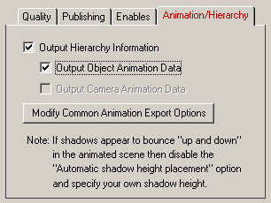
Output Hierarchy Information
If this option is enabled (checkmarked) then transformation hierarchy will be output to the MTS3 file. This is a basic requirement to output object animation data.Output Object Animation Data
If this option is enabled (checkmarked) then scale/rotate/translation object animation data will be output if it is present. This object requires that the "Output Hierarchy Information" checkbox is also enabled.Output Camera Animation Data
If this option is enabled (checkmarked) then camera animation data will be output if it is present.Modify Common Animation Export Options
Pressing this button will display the Common Animation Export Options dialog box. This dialog box controls how internal animation data is optionally re- sampled during its export to a MTS3 file. Please note that all quaternion rotation data is always resampled to Euler format during export, and YXZ ordered Euler rotations (such as from Lightwave) are always resampled to XYZ Euler order.


![[Page1]](/conv/mtssml1.gif)
![[Page2]](/conv/mtssml2.gif)
![[Page3]](/conv/mtssml3.gif)
![[Page4]](/conv/mtssml4.gif)
![[Page5]](/conv/mtssml5.gif)