

| You are here: Home » Import CAD Formats » AutoCAD-Revit-Navisworks (DWF-3D) |
Support: 905-672-9328 Copyright © 2024 Okino Toronto, Ontario, Canada. |

The is one of Okino's key import converters which allows Autodesk Softimage dotXSI model files to be loaded from the Autodesk Softimage (XSI) animation program (or any other program which exports the dotXSI file format). It is a highly complex, production-worthy animation/skinning/CAD/DCC pipeline for Softimage users refined for well over a decade.
This dotXSI importer will run inside any Okino compliant program such as the stand-alone PolyTrans or NuGraf programs, PolyTrans-for-3dsMax and PolyTrans-for-Maya native plug-in systems.
Please also refer to the corresponding XSI export converter.
- Support for dotXSI 3.0, 3.5, 3.62, 5.x and 6.x file format standards (NOTE: these file
format version numbers do not relate to the actual version of the Softimage program itself,
such as Softimage 7.x). The importer DLL is linked to the newest and current Softimage dotXSI (Crosswalk) SDK for file
format and version compatibility.
- Polygonal meshes with vertex normals, (u,v) texture coordinates and vertex colors. Exploded meshes inside one model template are compressed back together again.
- Support for the dotXSI extended templates: XSI_BasePose, XSI_Mesh, XSI_PolygonList, XSI_Shape, XSI_Transform, XSI_TriangleList, XSI_TriangleStripList and XSI_VertexList.
- Support for importing the XSI shader tree structures, image nodes and textures. The importer 'walks' each Softimage shader tree and turns them into layered Okino material definitions that can be exported to other 3D file formats and animation packages that don't have shader tree support.
- NURBS trim curves on NURBS surfaces (from dotXSI 3.6 or newer files).
- Independent NURBS curves and curve lists.
- Excellent and robust support for Softimage "skinned mesh" and skeleton import, which ties into the Okino Arctic toolkit. This allows PolyTrans to cross convert skinned mesh, animation and skeleton data between Softimage,
Maya, 3ds max, Lightwave, DirectX, Collada, U3D and FBX file formats, with proper bone re-orientation, off-axis scaling removal, and so forth.
- Lights, cameras and their related parameters.
- Object, camera, light and material animation import, as well as hierarchy processing and import.
- Fully recognized and imported "Softimage instancing" of model nodes. dotXSI instances are imported as proper Okino master/object instancing. Also handles incorrectly written dotXSI files from Softimage 4.0 (or older) where one model node has both an instance reference and real geometry.
- Automatic bitmap conversion and automated modification of imported shading coefficients.
- Built on the Softimage "semantics" parser toolkit to ensure high fidelity import, robustness and longevity of this importer code.
dotXSI files of version 3.5 and newer define materials using a shader tree of nodal connection. This importer will examine each shader tree and extract layered material definitions which are compliant with Okino's shader system and other downstream file formats and animation programs. Only the shader connections method below are handled by this importer.
An example of the type of shader connections supported by this importer is shown below:
- Illumination nodes that can feed into the "Surface" plug of the Material includes: Phong, Blinn and Lambert.
- The ambient, diffuse, specular, incandescence, and transparency input plugs of the illumination nodes recognize 2D texture images, as well as mixer nodes.
- Mixer nodes will accept static colors, 2D textures, other mixers,
illumination shaders, and a few other shader nodes as input. Weights
can be connected to a 2D texture, if that texture is also the input,
or it can go through a channel picker and
conversion node. The channel picker and
conversion node can also be used as input in the mixer.
- The bump map input plug of the illumination nodes must be a 'Color2Vector' node which itself is fed from the bump map texture. Bump mapping is also supported through bump map generator nodes, attached directly to the material
- A 2D texture image can also be fed into the "Environment" plug of the Material for spherical environment mapping.
- Material parameters which are imported include:
- Ambient, diffuse, specular and incandescence colors.
- Phong shininess or Blinn roughness
- Transparency and index-of-refraction
- Ambient, diffuse, specular and incandescence colors.
Other examples of supported shader trees that can be imported are as follows:
(Click image for full resolution version)
(Click image for full resolution version)
(Click image for full resolution version)
- The corresponding Softimage .xsi file export converter.
Strip off File Paths from Bitmap References
If this option is disabled then absolute filepaths will be stripped off from the bitmap references, else the file paths will remain unmodified.Report importer warning messages
If this checkbox is check-marked then warning messages will be displayed during the parsing phase.Report Statistics About the Geometry File
If this checkbox is check-marked then parsing statistics will be displayed in the message window after the Softimage dotXSI file has been imported.Output Parsing Information to File 'debugxsi.txt'
If this checkbox is check-marked then the dotXSI parser warnings and error messages will be output to the file 'debugxsi.txt'.Reattach Skinned Meshes to 'World' Root Node
This option solves problems when importing skinned meshes which have animation and/or hierarchical transformations on them. Normally a skinned mesh is transformed only by its corresponding skeleton. But there are cases where a skinned mesh may be located within a hierarchy which has animation or other transformations above it in the hierarchy. In such cases it is sometimes better to move the skinned mesh out of the hierarchy up to the top-most "world" root node so that no other transformations affect it.Report Shader Translation Warnings
If this checkbox is check-marked then warning messages will be printed if dotXSI shaders are encountered which cannot be imported since they are either understood or not supported.Ignore Unrecognized Shaders
If this checkbox is check-marked then any shader encountered which is not entirely recognized will be ignored and not imported. If this checkbox is disabled then the importer will attempt to extract as much information from the shader node that it can and continue parsing. The default is to ignore unrecognized shaders.Transform Cameras
If this checkbox is check-marked then each imported camera's location will be transformed by the parent model node it is attached to. This is the default. If this checkbox is disabled then the camera will not be transformed to the location of its hierarchical parent and a warning message will be reported.Transform Lights
If this checkbox is check-marked then each imported light's location will be transformed by the parent model node it is attached to. This is the default. If this checkbox is disabled then the light will not be transformed to the location of its hierarchical parent and a warning message will be reported.Bump Mapping Intensity Divisor
This parameter affects the translation of a bump map's intensity. The numeric value in this type-in box defines how much smaller the Softimage bump map intensity will be scaled.Assumed Ambient Shading Coefficient
This type-in box allows you to specify the ambient shading coefficient for all materials imported from the dotXSI file. The default value is 0.3, and the valid range is 0.0 (no ambient) to 1.0 (100% ambient contribution). If the imported model appears to be "too washed out" then set this value lower.Shading Coefficient Modifications
See below for a longer explanation of these combo boxes. In general, these combo boxes allow the key material attributes to be tweaked during import. This might be necessary, for example, if the imported objects appear too ambient, or too luminous.
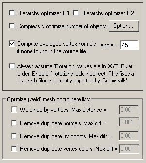
Hierarchy Optimizer # 1, Hierarchy Optimizer # 2
These options provide methods to remove redundant hierarchy nodes ('NULLs') from the imported file. Optimzier # 1 removes runs of empty folders, as well as folders with no children. Optimizer # 2 is simpler, deleting empty folders which only have 1 geometry object in them.Compress & Optimize Number of ObjectsThe primary purpose of this function is to collect together all objects that are parented under a single folder icon (yellow folder icon = empty instance, red folder icon = empty object) and turn those objects into a single new object definition. This operation will be repeated for each and every selected folder in the scene.Compute averaged vertex normals if none found in the source file.You would normally enable this function when importing CAD files. CAD modelers often export out a 3D model as a grouping series of "face" meshes. While you might have a simple object like a "sphere" in a CAD program, it might be exported in its BREP format of a dozen "face" meshes. This is what most users don't want to see in a destination animation package. In such cases simply enable this option and the dozens of face meshes will be combined back into one mesh, based on hierarchy in the imported file.
Vertex normals are vectors contained at each polygon vertex that are used to make the polygon mesh 'appear to be smooth' in a 3D rendering program. If such vertex normals do not exist on a polygon mesh object then it will render 'faceted' and not smooth.Always assume 'Rotation' values are in 'XYZ Euler Order'If this checkbox is enabled then new vertex normals will be computed for a polygon if it does not have any vertex normals already. The smoothing criterion is based on the angle between abutting polygons; common smoothed vertex normals will be computed if the angle between their geometric surfaces normals is less than the angle specified on the dialog box (which defaults to 45 degrees).
This option fixes a known bug with the dotXSI exporter of Autodesk Softimage. If you import a dotXSI file into Okino software (in particular a skinned mesh) and find that the rotations look wrong (such as a man's arm twisted backwards) then enable this checkbox.Optimize (weld) mesh coordinate listsExplanation: Okino has discovered a case where the dotXSI exporter of Autodesk Softimage will output a 'XSI_Transform' stating that the rotation values should be interpreted in the order other than XYZ. However, in reality the data provided in the file is actually in the XYZ rotation order. Enabling this option will cause Okino's dotXSI importer to always apply rotations in the 'XYZ' Euler order.
These options allow vertex XYZ coordinates, vertex normals, vertex uv texture coordinates and vertex RGB colors to be welded together, or in other words, duplicate entries removed from their respective lists based on a small tolerance value.Typically the 'Weld nearby vertices' option is used most often from this list of vertex optimizers. In particular, it is important to enable it if you also have the 'Compute averaged vertex normals' option enabled (see above), as it may not work unless all the vertices of a mesh are first welded together (made coincident and shared).
Weld nearby vertices
If this checkbox is enabled (check-marked) then the vertex welding operation will be applied to all polygon vertices once the dotXSI file has been read into memory and the objects created. Vertex welding collapses adjacent vertices which are within a distance less than or equal to the threshold value specified on the dialog box.Remove duplicate vertex normals. Max diff = #Note that welding of vertices can only occur within a single object and not between different objects.
Note: Do not enable this checkbox if any of your meshes have skinning/envelopes on them, as the welding process will cause the skinning to become invalid.
'Max distance' Type-In
If the distance between two vertices is less than or equal to this number, and the "Weld nearby vertices" checkbox is check-marked (enabled) then the two vertices will be collapsed (welded) into one.This is the same as the 'Weld nearby vertices' function except that it combines redundant vertex normals that are within a certain numerical threshold of each other.Remove duplicate texture coords. Max diff = #This is the same as the 'Weld nearby vertices' function except that it combines redundant 2D vertex uv texture coordinates that are within a certain numerical threshold of each other.Remove duplicate vertex colors. Max diff = #This is the same as the 'Weld nearby vertices' function except that it combines redundant vertex RGB colors that are within a certain numerical threshold of each other.
This following options control the import of NURBS curve from the XSI_CurveList template of the dotXSI file.
Display NURBS Curve Control Point Locations on UI
If this checkbox is check-marked then the control point (CV) locations used by any 3D independent NURBS will be displayed. This option is only applicable when viewing imported NURBS curves within the Okino stand-alone software.Specify closed NURBS curves as being renderable
If a NURBS curve (or series of NURBS curves) form a closed loop, and this option is enabled, then those curves will be flagged as being "renderable". This only has significance to the Okino stand-alone PolyTrans or NuGraf software in which case such "renderable" curves can be scanline or ray traced rendered as a 3D surface and not just a 3D curve.Also, if the curve loop is set as renderable, then it can be (optionally) converted into a trimmed NURBS 3D surface when being re-exported to other 3D programs, such as Maya or 3DS MAX.
Always consider multiple curves as one closed loop
The dotXSI file format allows multiple NURBS curves to be embedded into a single curve list entity (XSI_CurveList). These multiple curves could be interpreted as distinct separate curves or one continuous curve. If this option is enabled then the multiple curves will always be considered as one continuous loop.Import multiply curves per list as separate objects
The dotXSI file format allows multiple NURBS curves to be embedded into a single curve list entity (XSI_CurveList). If this option is enabled then each curve contained inside a dotXSI file curve list will be imported as its own unique object definition. If this option is disabled then all curves will be imported into a single object definition (which is the default option).Enable NURBS curve cleansing during import
If this option is enabled then the NURBS curves will be "cleansed" (multiple knots removed as best can be done, and the knot vector is clamped). This option is enabled by default.
The following checkboxes allow all or only some parts of the dotXSI file to be loaded:
Polygon Meshes
If checkmarked, then load in all of the polygon mesh geometry (triangle or polygon lists). You can also selectively specific portions of the mesh to load:
- Vertex Normals - Load in vertex normals.
- Vertex Texture uv's - Load in texture uv vertex coordinates.
- Vertex Colors - Load in vertex colors.
Envelopes (skins)
"Mesh skinning" (or enveloping as it is known to Softimage users) is the process of deforming a single skin mesh with a skeleton (in the dotXSI file the skeleton is represented by the NULL nodes which define the pivot point and orientation of each invisible bone). The contribution of each bone of the skeleton to the deformation of a vertex in the mesh is controlled by vertex weights. If this option is enabled then a mesh will be bound to one of more NULL nodes from the dotXSI file (which represent the bones or joints of the skeleton) via transformation matrices and weight values.NURBS Surfaces
If checkmarked, then load in all of the NURBS surface geometry.NURBS Trim Curves
If checkmarked, then load in all of trim curve data that is associated with each NURBS patch. This option is not available in certain older versions of the dotXSI file format and of the Softimage software itself.Cameras
If checkmarked, then load in the camera definitions from the dotXSI scene file.Lights
If checkmarked, then load in the lights.Materials
If checkmarked, then load in the materials.2D Material Textures
If checkmarked, then load in the textures that are referenced by a dotXSI material.
These options relate to the import of object, camera, light and material animation fcurves from the dotXSI file.
Object Animation
If checkmarked, object animation is imported from the Softimage dotXSI file. Supported fcurves are: explicit location, explicit scaling and explicit rotation. Animation on a path is presently not supported.Camera Animation
If checkmarked, camera animation is imported from the Softimage dotXSI file. Supported fcurves are: position (look-from), interest (look-at), roll and field-of-view.Light Animation
If checkmarked, light animation is imported from the Softimage dotXSI file. Supported fcurves are: position (shine-from), orientation (shine-direction), interest (look-at) and color.Material Animation
If checkmarked, material animation is imported from the Softimage dotXSI file. Supported fcurves are: ambient, diffuse, specular and emissive colors (as separate R, G and B function curves), and Phong power.Perform Keyframe Reduction
Softimage dotXSI files, v3.6.2 and newer, allow many aspects of its transformation matrix to be animated. However, most downstream file formats only accept scale, rotate and translation keyframe animation. To overcome this major problem this dotXSI importer incorporates Okino's "Arctic" toolkit. This specialized toolkit allows the matrices to be deep resampled into explicit scale, rotate and translation function curves. However, by doing so, an overabundance of keys are often created.If this option is enabled then an algorithm will be applied to the new imported keyframe lists to reduce the number of redundant keys. The type-in values determine the threshold criteria for keeping or removing a key from a list.
If this option is disabled then no keyframe reduction will be done. If you want very accurate animation import then do not enable this option, or else keep the threshold values at minimum values to keep the degree of reduction low.
Distance Threshold
This numeric value indirectly controls how many redundant keyframes are to be removed from the re-sampled keyframe list. Higher values will cause more keyframes to be removed. This value is the maximum 'distance' the new keyframe list is allowed to deviate from the original re-sampled keyframe list. Take for example a sphere that is animated along a path; if this threshold value is set to 0.5 distance units then redundant keyframes of the animated path will be removed until such point that the sphere begins to deviate by more than 0.5 units from its ideal location. In other words, if the value is set to 0.5 then you are guaranteed that the new reduced keyframe list will move the sphere along the same path in space, except that the sphere is allowed to deviate by 0.5 units from its original path. Smaller numbers will make the sphere adhere closer to its original path, but at the expense of retaining more keyframes.Angular Threshold (degrees)
This is the same as the previous numeric value except that it applies to reduction of quaternion and Angle/axis rotation keyframe lists. The value is measured in degrees. For example, if set to 5.0 then redundant keyframes will be removed from a keyframe list until such point that a rotation angle begins to deviate from its ideal angle by more than 5 degrees. Small numbers (such as 1.0 and 0.5) will cause less deviation and more precise rotation conversions, but at the added expense of retaining more keyframes.
These combo boxes provide hands-on control over how imported material shading parameters should be modified so that the imported model can be rendered nicely in a photo-realistic rendering program. All too often the imported model appears "too diffuse" resulting in rendered images that are washed out or with no gradual shading effects visible. The two combo boxes and the single numeric type-in box provide you good control over the diffuse, specular and luminous shading coefficients imported into PolyTrans/NuGraf, as well as the opacity of the material and Phong shininess value.The first drop-down combo box selects which of these shading parameters you want to modify. Each shading coefficient has its own operation which can be selected (the second combo box) and an optional numeric type-in value (the third data entry text input). The following describes the various shading parameters that can be controlled:
- Diffuse Coefficient: This controls the amount of color reflected from an object based on the direct light shining on it. A good default value is 0.4 and ideally ranges from 0.0 to 1.0. Some programs have a diffuse shading coefficient parameter (NuGraf/PolyTrans, etc) while others do not (3D Studio). If an export file format does not support a diffuse shading coefficient then this value will be multiplied into the diffuse shading color itself.
- Specular Coefficient: This controls the intensity of the highlight color on an object. A good default value is 0.7 and ideally ranges from 0.0 to 5.0. If an export file format does not support a specular shading coefficient then this value will be multiplied into the specular shading color itself.
- Luminous Coefficient: This controls how much color is added directly to an object, irrespective of any light which shines on it (the higher the value, the more the object will appear to glow). In general you should keep this value at 0. If an export file format does not support a luminous shading coefficient then this value will be multiplied into the luminous shading color itself.
- Opacity: This is the inverse of transparency. 0.0 will make the object fully transparent, while at 1.0 the object will be fully opaque.
- Phong Shininess: This controls the width of the specular highlight seen on an object. An ideal range is 6 (very wide) to 300 (very narrow). The default is 32.
For each material shading parameter, several actions can be performed on it during the import process:
- Do Not Import: The shading parameter is not imported at all. No value is imported nor sent to PolyTrans/NuGraf. Thus, the default material shading parameter value (as set inside PolyTrans/NuGraf) will be used instead.
- Import Unchanged: The shading parameter is imported as is, with no change.
- Set and Use Default: The shading parameter is set to some "good" default value (as determined by the import converter). This default value will be shown in the type-in box.
- Set to Specific Value: The imported shading parameter will be overridden with the user specified value of the numeric type-in box.
- Import and Crop by: The shading parameter is imported and will remain unchanged if it is less than the numeric type-in value shown on the dialog box. If it is greater, then the imported value will be clamped to be no greater than the numeric type-in value. This is a good operation, for example, if you do not wish for the ambient shading coefficient to be greater than 0.3.
- Import and Scale by: The shading parameter is imported and multiplied by the numeric type-in value shown on the dialog box
- Normalize Color and Coefficient: This option only applies for the ambient, diffuse, specular and luminous shading coefficients and their respective RGB colors. This option is a hybrid approach which tries to automatically "guess" at a proper shading coefficient value given the raw (and corresponding) color imported from the file. As mentioned, the shading coefficient is needed to create nice looking (nicely shaded) images in a photo- realistic rendering program. If this option is chosen, then the specific shading coefficient will be derived directly from the relative intensity of the imported color which corresponds to this shading coefficient (diffuse color for diffuse shading coefficient etc.). For example, if the imported diffuse color is (0.4, 0, 0), which is 40% of full-bright red, then the diffuse shading coefficient will be set to 0.4 and the diffuse color will be modified to be (1, 0, 0). When the new color (1,0,0) and the new shading coefficient (0.4) are multiplied together, it results in the original color imported from the file (0.4, 0, 0). In general you may wish to use the "Set and Use Default" option to get good rendered results.