

| You are here: Home » Import CAD Formats » Solid Edge |
Support: 905-672-9328 Copyright © 2026 Okino Toronto, Ontario, Canada. |
|
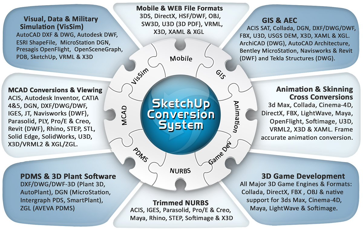
This import converter reads in .skp and .skb SketchUp files. It is a full featured importer with many useful and productive processing options. A good source of free SketchUp models can be found on the Google "3D Warehouse" WEB site.Okino's SketchUp import conversion system intelligently and robustly converts SketchUp models (including embedded texture images) into a plethora of professionally supported 3D export file formats and programs such as: 3ds Max (via PolyTrans-for-3dsMax), Maya (via PolyTrans-for-Maya), CINEMA 4D, Collada, DirectX, DXF/DWG, DWF-3D, Electric Image FACT, FBX, glTF, HOOPS HSF, JT, LightWave, OpenFlight, OpenGL, PLY, Rhino, STL, U3D (from PDF), USD, VRML1+2+X3D, XAML, XGL, Wavefront OBJ and others (if you don't see your required format then just email us and we'll explain the standard conversion route for that program or file format).
Click for larger image.
Note: some conversion paths shown in this image are uni-directional only.Please also refer to the corresponding SketchUp export converter.
The SketchUp import/export conversion system is provided as part of the base-level PolyTrans and NuGraf programs.
If you wish to export to Collada, or Google Earth, then please also refer to Okino's extensive Collada implementation (which includes refined and special support for Google Earth).
SketchUp is a popular 3D design product originally developed by @Last Software (http://www.sketchup.com) and now owned by Trimble, Inc. Okino recognized the growing popularity of SketchUp (well before it was purchased by Google and then Trimble) and as such we worked directly with the original SketchUp developer to create the first set of independent, professional and fully compliant SketchUp 3D converters outside of the SketchUp program itself. Okino's SketchUp conversion system is used throughout the 3D production world by everyone from Disney to LucasFilm to Sony Productions to NASA and many people just like yourself.
- Download and install the stand-alone Okino PolyTrans or NuGraf combined demo.
- Optionally run the "Super Installer" for 3ds Max or Maya integration.
- Execute the stand-alone PolyTrans or NuGraf program, PolyTrans-for-3dsMax within
3ds Max or PolyTrans-for-Maya within Maya.
CINEMA-4D conversions are always to be done inside
of the Okino stand-alone software and never within CINEMA-4D itself.
- Execute the Okino SketchUp importer and choose the desired .skp file. Use all default importer options.
- Choose and execute the desired destination Okino exporter. Use all default options in most cases (you are not compelled
to change the options on an Okino importer and exporter just because they exist).
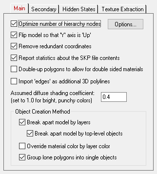
General Processing Options
Optimize number of hierarchy nodes
If this checkbox is enabled then redundant grouping folders will be removed from the hierarchy. This will make the hierarchy easier to view and manipulate. It is enabled by default. Press the "Options" button to modify the parameters of this processor.Flip Model so that Y Axis is 'Up'
If this checkbox is enabled then the model will be reoriented so that the Up axis of the model will be aligned with the positive Y axis (which is used by the converter) instead of the positive Z axis.Remove Redundant Coordinates
If this checkbox is enabled then an algorithm will be invoked to remove redundant vertices, normals and uv texture coordinates from each imported mesh object.Report Statistics About the SketchUp File Contents
If this checkbox is check-marked then parsing statistics will be displayed in the message window after the SketchUp file has been imported.Double-up polygons to allow for double sided materials
If this checkbox is check-marked then SketchUp polygons which have a unique and different "Front" and "Back" material will be imported as 2 polygons of opposite orientations, each of which will be assigned the corresponding front and back materials. The 2 polygons will be made very close to each other but not completely overlapping.NOTES:
- This can potentially double the number of polygons in the scene.
- Doubling up polygons is not common and generally is shunned upon. Most OpenGL displays will show doubled-up polygons with a "comb effect" in which the polygons tend to cancel each other out.
If this option is disabled then only the "front" materials will be assigned to the polygons specified in the SketchUp file, and no doubling of polygons will occur.
Import 'edges' as additional 3D polylines
SketchUp allows for thin lines on each model to give the impression of outlines. If this checkbox is enabled then these character lines will be imported as "polyline" geometry - such geometry cannot be rendered since it has no 3D area, and in some cases polyline geometry cannot be converted to other 3D file formats.Assumed ambient shading coefficient
This type-in box sets the intensity of the default ambient shading coefficient for the source SketchUp file. The SketchUp file does not specify the amount of ambience in the scene so that value is specified by this type-in number. Normally you will want to keep it at 0.3.Object Creation Method
The first two primary checkboxes determine how the geometry of the SketchUp file will be imported and exploded into a unique set of Okino objects, in an optional hierarchy.If all 2 checkboxes are disabled then the SketchUp file will be imported as a single object.
Break Apart Model by Layers
If this checkbox is enabled then the polygon meshes of the source file will be broken apart in to new objects, each grouped by the layer to which each polygon is associated.Break Apart Model by Top-Level Geometry Objects
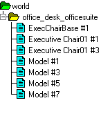
If this checkbox is enabled then the polygon meshes of the source file will be broken apart according to each top-level object from the SketchUp file, ignoring how the children of each of those top-level objects are structured.Override Material Color by Layer ColorFor example, relating to the hierarchy shown above, choosing this option will compress all the children together into these 4 distinct top-level objects:
Mesh object "M1" Mesh component "chair" Mesh component "chair" Mesh for Group "G1" and all of its childrenAs a real example, the following shows the imported flat hierarchy from the SketchUp file called office_desk_officesuite.skp.
 If this checkbox is enabled then polygons which have been grouped "by layer" will take their color from the layer's color (in the SketchUp file) rather than from the material definition. This is disabled by default. The "Break Apart Model by Layers" option must be enabled for this to take effect.
Group Lone Polygons into Single Objects
If this checkbox is enabled then any polygons which are not associated with layers, groups, instances or component definitions will be grouped together into a new, single mesh. This reduces the amount of clutter in the imported scene.
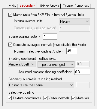
Match units from SketchUp File to Internal System Units
These options determine what will be done when the units defined in the SketchUp file do not match current internal system units. If the units do not match, the SketchUp importer will rescale the imported geometry based on the ratio between the SketchUp units and the internal system units.If this checkbox is enabled then the SketchUp importer will rescale all imported geometry so that the units of the SketchUp file can be made to match the units of the internal NuGraf/PolyTrans database. If the checkbox is disabled then the geometry will be imported unchanged and untouched, meaning that its scale may be "incorrect".
NOTE: the final statistics shown in the message window will also include the units found in the source SketchUp file.
Internal System Units
This drop-down combo box specifies the current units system in effect within the internal NuGraf/PolyTrans 3d database. It defaults to meters. What you need to do is select an appropriate entry from the drop-down combo box which matches the system units used by your destination program: for example, set it to Centimeters for Lightwave, Inches for 3DS MAX, Centimeters for Maya, etc.
None No units; never do any geometry scaling Custom Custom units are in effect. See below Microinches 1e-6 inches Mils 1e-3 inches Inches 0.0254 meters Feet 12 inches Miles 63360 inches Microns 1e-6 meters Millimeters 1e-3 meters Centimeters 1e-2 meters Meters Kilometers 1e+3 meters Custom Units in "Units Per Meter"
If the drop-down "Internal System Units" combo box is set to "Custom", then this edit text control defines the "units per meter" scale factor for the custom unit system.Compute averaged normals
If this checkbox is enabled then new vertex normals will be computed for each mesh. For this option to take effect you must disable the "Vertex normals" selective loading checkbox.The smoothing criterion is based on the angle between abutting polygons; common smoothed vertex normals will be computed if the angle between their geometric surfaces normals is less than the angle specified on the dialog box (which defaults to 45 degrees). Note that the vertices will be welded together prior to this smoothing operation taking place.
Shading Coefficient Modifications
See below for a longer explanation of these combo boxes. In general, these combo boxes allow the key material attributes to be tweaked during import. This might be necessary, for example, if the imported objects appear too ambient, or too luminous.Geometry Automatic Rescaling Method
This combo box provides access to a useful mechanism which automatically rescales the imported mesh geometry to a size best needed by other 3D software packages. For example, a Solid Edge test file imported into this converter had a size of only 0.05 units across (probably due to the implicit modeling units used within the Solid Edge program); this model was much too small (in extents) for other 3D programs to manipulate properly. To overcome these scaling issues, this combo box can be used to automatically resize any imported model data to a useful size, such as scaled to easily fit inside a box of 2x2x2 raw working units (which is the default). The various options are described as follows:Do Not Resize the Scene
No resizing is done to the imported data.Resize to 1x1x1 units
Resize to 2x2x2 unitsThe model data is automatically scaled up in size, or scaled down in size so that its worldspace extents fits inside a 1x1x1 or 2x2x2 sized unit cube. The latter is the default.Resize to User Defined Absolute Size
The model data is automatically scaled up in size, or scaled down in size so that its worldspace extents fit inside a cube whose size is user defined by the type-in value shown on the dialog box. For example, if you enter the value 20 then the imported data will be resized so that its maximum extent in one or more dimensions is 20 units.Scale Larger by User Defined Factor
Scale Smaller by User Defined FactorThese options allow the imported model data to be scaled larger or scaled smaller by an absolute number. For example, if you select the larger option and enter 10 into the type-in box, then the imported model will be scaled 10 times larger during the import process.Selecting Loading
These options allow specific portions of the SketchUp file to be imported.Vertex Texture Coordinates
If checkmarked, vertex uv texture coordinates will be imported. These texture coordinates (if provided) are necessary in order for 2d bitmap textures to be applied to objects.Vertex Normals
If checkmarked, vertex normals will be imported. SketchUp files contain vertex normals which are used to make the imported object appear smooth when shaded.Materials
If this checkbox is enabled then materials will be imported and assigned to the objects.
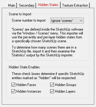
Scene Number to Import
'Scenes' are defined inside the SketchUp software via the 'Window / Scenes' menu. This importer will optionally import and use the per-entity hidden states (face, group or instance) and per-layer hidden states from a specifically chosen SketchUp scene.This combo box determines which scene number from the SketchUp file to load. 32 are listed in the drop-down combo box at all times regardless of how many there are defined in the .skp file. To determine how many scenes are defined in the .skp file, either examine it within the SketchUp program, or import the .skp file using the Okino importer and look at the final scene statistics.
If you don't wish to import the hidden states from a specific SketchUp scene, set this combo box to Ignore Scenes.
Hidden State Enables
SketchUp allows hidden states to be applied to entities (faces, instances or groups) and/or per-layer.If a 'face' is hidden (a polygon) then it will not be imported.
If an instance, group or layer is hidden then its corresponding node in the imported scene will be set to 'hidden'.
NOTE: If you choose a specific scene to import (via the combo box explained further up in this help) then the hidden states defined in that specific SketchUp scene will be used instead of the normal hidden states.
Hidden Faces
If this checkbox is enabled then per-face (per-polygon) hidden states will be imported and respected from the source file. A face (polygon) which is hidden will not be imported.If this checkbox is disabled (un-checked) then all faces will be imported regardless of their hidden state.
Hidden Instances
If this checkbox is enabled then any SketchUp instance which is tagged as being "hidden" will be imported as an Okino "instance" with its hidden state set to 'On'.Hidden Groups
If this checkbox is enabled then any SketchUp group which is tagged as being "hidden" will be imported as an Okino grouping folder with its hidden state set to 'On'.Hidden Layers
If this checkbox is enabled then any SketchUp layer which is tagged as being "hidden" will be imported as an Okino grouping folder with its hidden state set to 'On'.Note: you will need to enable the "Break Apart Model by Layers" option on the main panel.
SketchUp files embed their texture mapping bitmap images directly inside the .skp or .skb files. These images need to be extracted before they can be used in other programs. This panel describes how those texture maps will be extracted and converted back to bitmap files on disk.Note: The directory where the files are to be written must have write permissions.
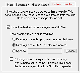
Extract embedded texture images from SketchUp file
If this option is enabled then the texture maps embedded in the SketchUp file will be extracted to stand-alone bitmap images on disk. If disabled, then no texture maps will be extracted and you will not see the model with applied textures.Base directory to save extracted files
These radio button options define where the extracted texture map images will be written to disk.Directory where this program was executed from
The extracted images will be saved in the directory where this program began execution (which is usually the same as where this program is located on disk). This is not a preferable option since this directory will eventually become cluttered with images extracted from SketchUp files.Directory where SketchUp input files are located
The extracted images will be saved in the same directory where the SketchUp input file was read from. This is the default but in general it is recommended that the images be placed into a unique sub-directory, such as when the "Put images into a Newly Created Sub-Directory" option is enabled.Specific
The extracted images will be saved in the directory indicated by the type-in edit box. If no directory is shown, or you want to change the current output directory, then the Browse button can be pressed to select the desired destination directory.Put images into a Newly Created Sub-Directory
If this additional checkbox is enabled then the newly extracted bitmap image files will be written into a new, unique sub-directory. The name of that new sub-directory will come from the name of the SketchUp file being imported. The main parent directory location is set via the "Base directory to save extracted files" option above.You would want to enable this option if you are importing 2 or more SketchUp files, as an example, and you do not want to have any filename collisions between them for the extracted texture maps. In other words, it may be possible that 2 different SketchUp files will create the exact same extracted texture map files on disk, even though they have different contents - in this case the second file will cause the previous file's texture maps to be overwritten unless we go and place them into their own unique sub-directories.
These combo boxes provide hands-on control over how imported material shading parameters should be modified so that the imported model can be rendered nicely in a photo-realistic rendering program. All too often the imported model appears "too ambient" or "too diffuse" resulting in rendered images that are washed out or with no gradual shading effects visible. The two combo boxes and the single numeric type-in box provide you good control over the ambient, diffuse, specular, luminous and reflection shading coefficients imported into PolyTrans/NuGraf, as well as the opacity of the material, its index of refraction (IOR) and Phong shininess value.
The first drop-down combo box selects which of these shading parameters you want to modify. Each shading coefficient has its own operation which can be selected (the second combo box) and an optional numeric type-in value (the third data entry text input). The following describes the various shading parameters that can be controlled:
- Ambient Coefficient: This controls the amount of color reflected from an object based on the ambient light in a scene. A good default value is 0.1 through to 0.3 and ideally ranges from 0.0 to 1.0. Some programs have an ambient shading coefficient parameter (NuGraf/PolyTrans, Electric Image, etc) while others do not (3D Studio). If an export file format does not support an ambient shading coefficient then this value will be multiplied into the ambient shading color itself.
- Diffuse Coefficient: This controls the amount of color reflected from an object based on the direct light shining on it. A good default value is 0.4 and ideally ranges from 0.0 to 1.0. Some programs have a diffuse shading coefficient parameter (NuGraf/PolyTrans, Electric Image, etc) while others do not (3D Studio). If an export file format does not support a diffuse shading coefficient then this value will be multiplied into the diffuse shading color itself.
- Specular Coefficient: This controls the intensity of the highlight color on an object. A good default value is 0.7 and ideally ranges from 0.0 to 5.0. If an export file format does not support a specular shading coefficient then this value will be multiplied into the specular shading color itself.
- Luminous Coefficient: This controls how much color is added directly to an object, irrespective of any light which shines on it (the higher the value, the more the object will appear to glow). In general you should keep this value at 0. If an export file format does not support a luminous shading coefficient then this value will be multiplied into the luminous shading color itself.
- Opacity: This is the inverse of transparency. 0.0 will make the object fully transparent, while at 1.0 the object will be fully opaque.
- Phong Shininess: This controls the width of the specular highlight seen on an object. An ideal range is 6 (very wide) to 300 (very narrow). The default is 32.
For each material shading parameter, several actions can be performed on it during the import process:
- Do Not Import: The shading parameter is not imported at all. No value is imported nor sent to PolyTrans/NuGraf. Thus, the default material shading parameter value (as set inside PolyTrans/NuGraf) will be used instead.
- Import Unchanged: The shading parameter is imported as is, with no change.
- Set and Use Default: The shading parameter is set to some good default value (as determined by the import converter). This default value will be shown in the type-in box.
- Set to Specific Value: The imported shading parameter will be overridden with the user specified value of the numeric type-in box.
- Import and Crop by: The shading parameter is imported and will remain unchanged if it is less than the numeric type-in value shown on the dialog box. If it is greater, then the imported value will be clamped to be no greater than the numeric type-in value. This is a good operation, for example, if you do not wish for the ambient shading coefficient to be greater than 0.3.
- Import and Scale by: The shading parameter is imported and multiplied by the numeric type-in value shown on the dialog box
- Normalize Color and Coefficient: This option only applies for the ambient, diffuse, specular and luminous shading coefficients and their respective RGB colors. This option is a hybrid approach which tries to automatically guess at a proper shading coefficient value given the raw (and corresponding) color imported from the file. As mentioned, the shading coefficient is needed to create nice looking (nicely shaded) images in a photo-realistic rendering program. If this option is chosen, then the specific shading coefficient will be derived directly from the relative intensity of the imported color which corresponds to this shading coefficient (diffuse color for diffuse shading coefficient etc.). For example, if the imported diffuse color is (0.4, 0, 0), which is 40% of full-bright red, then the diffuse shading coefficient will be set to 0.4 and the diffuse color will be modified to be (1, 0, 0). When the new color (1,0,0) and the new shading coefficient (0.4) are multiplied together, it results in the original color imported from the file (0.4, 0, 0). In general you may wish to use the Set and Use Default option to get good rendered results.