| Import Format | Ext | Mat | Hier | uv | VC | L&C | NURBS | Anim | Skel | Skin |
| 3D Studio R1-R4 | .3ds |  | | | | | | | | |
Note: Please do not confuse the .3ds format with the 3ds Max .max format. You will find throughout the 3D industry that some companies refer to .3ds as the "3ds Max file format" but this is not true. The native file format of 3ds Max is the .max format, whereas .3ds is just a legacy import/export file format ported over to 3ds Max by Tom Hudson during the transition from 3D Studio R4 back in 1993 and 1994. DO NOT use the .3ds file format to convert to/from 3ds Max but rather use Okino's dedicated PolyTrans-for-3dsMax plug-in system for 3ds Max. The .3ds file format was the native file format of the old Autodesk "3D Studio R1-R4" software, which was popular up to about 1996 before its successor (3ds Max) replaced it. Having been around since the very late 1980's, it has grown to become an industry standard for transferring models between 3D programs, or for storing models for 3D resource catalogs (similar in status to Wavefront OBJ as a model archiving file format). Suggestion: Do not use the .3ds format to transfer data to/from 3ds Max (especially for huge CAD datasets). There are many people who continue to do this. The best method is to use the directly integrated PolyTrans-for-3dsMax plug-in system. However, .3ds is no longer an ideal file format as it once was. The .3ds format has several serious shortcomings, many of which probably stem from the fact that 3D Studio R1 grew out of Tom Hudson's mid-80's "CAD-3D" on the Atari platform: - All meshes must be triangles.
- All texture filenames are limited to 8.3 DOS character lengths.
- The number of vertices and polygons per mesh is limited to 65536.
- Accurate vertex normals cannot be stored in the .3ds file. Instead "smoothing groups" are used so that the receiving program can recreate a (hopefully good) representation of the vertex normals. This is still a hold-over legacy for many animation programs today which started in the 1980's (3ds Max, LightWave and trueSpace still use smoothing groups, and Maya up to v2.51).
- Object, light and camera names are limited to 10 characters. Material names are limited to 16 characters.
- Directional light sources are not supported.
Okino was the first to fully reverse engineer the .3ds file format by 1993 and it became one of the most fundamentally important converters in our software, along with LightWave support by 1994. Okino's .3ds importer reads in and converts every aspect of a 3D Studio file including all geometry (+ proper smoothing group recognition and processing), all camera and object animation data (plus the ability to animate 'instances' of 3D Studio objects), all material attributes (including the proper translation of edge fall-off transparency), lights, cameras, view data, background color schemes and all other auxiliary data from a .3ds binary file. In addition, it handles all (u,v) texture coordinates and uniquely imports all of the 3D Studio texture mapping methods (2 texture color maps, bump maps, opacity maps, shininess maps, automatic planar & cubical environment maps, spherical environment maps and luminosity maps). As much as the .3ds file format is dated, you will find that the import of .3ds data into Okino software is one of the most reliable, robust and highly refined import pipelines available (from meshes right up to all of its animation data).
|
| 3MF (3D Manufacturing Format) | .3mf | | | | | | | | | |
The 3MF importer reads in 3D scene data from the industry standard 3D Manufacturing Format (3MF). Normally these files are used to export into 3D printing hardware devices but this importer was written as a means to read in and convert such 3MF files to other 3D software programs. The 3D Manufacturing Format (3MF) is a 3D printing file format spearheaded by Microsoft that allows design applications to send full-fidelity 3D models to other 3D applications, platforms, services and 3D printers. As explained by Microsoft, "3MF files describe the appearance and structure of 3D models for the purpose of manufacturing (3D printing)." It was primarily designed to replace the simplistic and aging 1987-era STL file format for 3D printing (as well as OBJ and VRML2). It is human readable and saved in a XML encoding. Some salient features of the 3MF importer: - Reading of 3MF supported polygonal geometry, part names, part hierarchy, basic material properties, layered texture maps and the extraction of JPEG+PNG bitmap images. Geometric and vertex normals will be computed for geometry without such information.
- Respect for, and the import of, geometry instancing, including 3 Okino scene and hierarchy optimizers.
- Layered texture map ("multi-property material") support with automatic extraction of JPEG and PNG bitmap images.
- Import of vertex colors.
- Intelligent overrides for the material colors and coefficients, to create "load and render" files.
- Support for the 3MF Core Specification and the 3MF Materials and Properties Extension.
- CAD-like units matching.
Please refer to the corresponding 3MF exporter.
|
3ds Max (via PolyTrans-for-3dsMax
native plug-in system) | .max | | | | | | | | | |
PolyTrans-for-3dsMax is to be considered one of Okino's "main software programs" which are utilized by a high percentage of Okino customers. As of the mid 1990's it became the first and still primary, professional conversion system for 3ds Max users. It allows all of the Okino 3D file formats to be accessed directly inside of 3ds Max. This is the only formal method by which the .max file format can be read/written by the NuGraf/PolyTrans software.Please note that it is not possible to import or export .max files directly from any program in the world except for 3ds Max itself. This has been a highy confusing issue for non-3dsMax program owners since 1994. The .max file format is not a pure 3D file format (as is the .3ds file format) but rather it contains a "state snapshot" of how the various plug-in modules with 3ds Max interact with each other to produce the final displayed mesh model. If you do not own a copy of 3ds Max then please have someone load a .max file into 3ds Max and export out either a .fbx, .3ds file or a .wrl (VRML2) file (VRML2 is always preferable). These can then be easily loaded into your copy of PolyTrans. Better yet, if that person owns a copy of PolyTrans, have them install the special PolyTrans plug-in module to 3ds Max and then export out an Okino .bdf file for you to load into your copy of PolyTrans. In order to read/write .max files we must run PolyTrans directly inside 3ds Max itself. This is because we need to have 3ds Max evaluate its "stack" of plug-in modules that operate on the base mesh. The evaluated output mesh is then sent to PolyTrans. Vice versa, we need to gain access to the core of 3ds Max to import data from PolyTrans and save it to the 3ds Max internal database. Please note that these special plug-in modules operate INSIDE 3ds Max itself and not inside the stand-alone NuGraf or PolyTrans software. These modules are NOT to be placed in the Okino 'vcplugin' directory. If you wish to transfer a 3ds Max .max file to NuGraf or PolyTrans, execute 3ds Max and export a scene file as an Okino ".bdf" file then execute NuGraf or Polytrans and load the .bdf file. The reverse direction can also be done by importing a .bdf file into 3ds Max. |
| Acclaim Motion Capture | .amc, .asf | | | | | | | | | |
This import converter reads in motion capture data from the Acclaim (.amc and .asf) file format. This file format describes animated skeletons in terms of bones, hierarchy and angle constraints.Acclaim .amc and .asf are legacy files from the 1990s and early 2000s that define motion capture data of animated skeletons in terms of bones, hierarchy and angle constraints. Okino software can import and export such Acclaim files relative to other animation systems such as 3ds Max, Maya, Cinema-4D, FBX, COLLADA, etc. |
| Biovision Motion Capture | .bvh | | | | | | | | | |
This import converter reads in motion capture data from the Biovision .bvh file format. This file format describes animated skeletons in terms of joints, hierarchy and angle constraints.Biovision BVH are legacy files from the 1990s and early 2000s that define motion capture data of animated skeletons in terms of joints, hierarchy and angle constraints. Okino software can import and export such BVH files relative to other animation systems such as 3ds Max, Maya, Cinema-4D, FBX, COLLADA, etc. |
| CINEMA 4D | .c4d | | | | | | | | | |
CINEMA 4D (C4D) is a well known and respected 3D DCC/Animation software program by MAXON Computer of Germany. C4D came to take on a much larger market share in the 2010's decade (and beyond) once other animation packages waned or went out of business. Okino has been MAXON's primary 3D conversion partner since 1998 and hence has very strong support for importing, exporting and converting C4D files without the need to have a local copy of C4D installed. Okino's CINEMA 4D import conversion system intelligently and robustly converts MAXON CINEMA-4D .c4d files into a plethora of professionally supported 3D export file formats and programs. It is a major technological advancement for CINEMA 4D users as it overcomes all the old limitations and problems with the free, built-in 3D converters which come with the CINEMA 4D program. Technically, this is the first professional conversion program which can read and write to the .c4d file format (some people may be confused of other programs which support CINEMA-4D v6 format but that has been obsolete since 1998). Refer to the following main documentation:
|
| COLLADA (best for Blender) | .dae | | | | | | | | | |
COLLADA (DAE) is a XML-based readable file format of the 2007/2008 era which had an original goal of allowing efficient cross conversion of 3D asset data between all of the major 3D DCC/Animation systems of that era. Many 3D software programs came to implement COLLADA but with varying levels of comformity and data reliability. COLLADA is more generally known as a polygonal mesh file format and not a MCAD/CAD/AEC/GIS format. Today people would usually use FBX over COLLADA, depending on the quality of the associated (and dated?) import/export converters. This is one of Okino's key DCC/Animation import converters which allows COLLADA .dae files to be loaded from any program which saves out COLLADA compliant files of the correct version and formatting. As a passing note, COLLADA has long been the best 3D file format to import/export with Blender and not FBX (which may surprise many Blender users). Okino has been involed with Blender since its very beginnings and hence tests its import/export converters under particularly stressful conversion conditions. Blender's COLLADA implementation properly supports geometry, hierarchy, part naming, instancing and material conversion. The two runner ups would be FBX and VRML2 but they are not recommended for use with Blender. Support is provided for polygonal mesh data with attributes (normals, vertex colors, uv texture coordinates and UV tangent vectors), 3D lines+linestrips+splines (linear and Bezier curves), skinned mesh and skeletons (mesh deformation via skinning), object + camera + light animation data, material data, texture maps and special 'extra' tag recognition. Please refer to the corresponding COLLADA exporter.
|
| DirectX | .x | | | | | | | | | |
The .X file format is the basic geometry format used by Microsoft's DirectX-3D real time rendering engine and it quite prevalent and popular in the 3D game development market.This import converter reads in ASCII and binary DirectX (.x) formatted files. Mesh data (with vertex normals, vertex uv texture coordinates and vertex colors), materials, texture references, hierarchy and object animation are all imported. In addition, vertex weights used for mesh/skeleton deformation skinning are imported and can be played back or re-exported via PolyTrans. The DirectX file format does not have support for lights, cameras or NURBS. It also has rudimentary material and texture mapping support. .x files are the native 3D file format of the legacy Microsoft DirectX v2/v3 API and 3D toolkit. They were generally associated with 3D gaming whereby low polygon meshes with skinning (deformation) and "animation sets/clips" were the required norm. At the time of its introduction in 1995 there really wasn't any other similar 3D file formats which supported these capabilities in one, well defined and easily accessible format. Direct3D shipped for the first time in the DirectX 2.0 SDK in June 1996 Historically, the DirectX technology was developed a company called Rendermorphics of the UK which Microsoft purchased in February 1995. As little known history, 3 companies in the UK developed advanced realtime rendering toolkits prior to 1995: Argonaut Software (BRender), Criterion Software (RenderWare) and Rendermorphics (Reality Lab). Microsoft was to license the Argonaut 3D toolkit but opted to purchase the entire Rendermorphics company instead, at the last moment. As these various toolkits often sold for $50k at that time, the other two competitors eventually went out of business once Microsoft started giving DirectX away for free. Okino knows of the .x file format well as it was the first company to properly and fully implement a DirectX importer and exporter, including full support for skinning and animation at a time when no other software provided such conversion support. |
| DXF R12 | .dxf | | | | | | | | | |
DXF and DWG are the native file formats of the Autodesk AutoCAD product since 1982. DWG is the binary file variation to the ASCII DXF file format. These files can be viewed by many programs including Autodesk's free DWG TrueView application. It is a closed file format but has been documented by the Open Design Alliance. If you wish to import from the most recent versions of the DXF and DWG file format (including embedded ACIS solids) then please use Okino's DWG import converter available in the "CAD/Pack" add-on. The base-package only provides support for DXF R12, which would be a viable option for anyone exporting this version of DXF from any CAD program. DXF can be considered the 'lowest common denominator' for 3D data file translation. DXF (ASCII) and its binary cousin (DWG) are the standard and native file formats of Autodesk's AutoCAD program. It has a very long history, starting in the early 1980's. Many 3D programs and modelers have some level of basic DXF import and export support, so if all else fails you can transfer mesh data to/from these programs using DXF (DXF does not support uv texture coordinates, vertex colors, materials, lights, texture maps, animation, etc.; just basic mesh geometry data). Please note: it is technically better to source from an Autodesk CAD program using DWF-3D file format and Okino's DWF-3D import conversion system (which is part of the CAD/Pack license) rather than to use the DXF or DWG file formats.
|
| Electric Image FACT | .fact | | | | | | | | | |
This import converter reads in raw FACT files from the Electric Image animation system. FACT files are also a common format to move scene data in and out of the Form/Z modeling program.The following are some of the features of this import converter: - All geometry is read in including the simple/complex geometry sub-data types, vertex normals, uv texture coordinates, vertex colors and tangent vectors,
- The complex hierarchy of the FACT file, including the preservation of linkage information and child/parent transformation information. Pivot points are properly derived from the linkage information.
- Material definitions (ambient/diffuse/specular colors, index of refraction, shading model, Phong highlight size and face opacity).
- Texture mapping information (filename, u/v scale, crop window information).
- All Electric Image texture projection methods (flat, cubic, spherical and cubical) are converted to equivalent NuGraf/PolyTrans texture projection methods.
|
| ESRI ShapeFile | .shp, .cshp | | | | | | | | | |
The ShapeFile format was defined by Environmental Systems Research Institute, Inc. (ESRI) for storing simple vector data elements, most often used for GIS datasets and GIS flat maps. The ESRI ShapeFile geometry import converter reads in the point, line and polygon-area geometrical vector data from a ESRI "Shape File". These files are often created using ESRI's ARC/INFO, ARC/VIEW and ARC/GIS. The file extensions are .shp (geometry data) and .cshp (ESRI ShapeFile project file, which makes reference to other .shp files on disk). 2D and 3D datasets are supported.
|
| FBX v5, v6, v7 | .fbx | | | | | | | | | |
This geometry import converter reads in Autodesk FBX v5, v6 and v7 files. It was the very first implementation of FBX conversion, long before Autodesk came to buy out the bankruptcy assets of Alias Research. This import converter allows support for all major features in FBX files including support for polygon meshes, NURBS patches, bicubic or linear patches, geometry hierarchy, lights, cameras, animation and mesh skinning:- Reading of all FBX supported geometry including polygons, NURBS and patches. Geometric and vertex normals will be computed for geometry without such information.
- Import of materials, textures, texture mapping, lights and cameras.
- Full object hierarchy import into NuGraf/PolyTrans with user selected hierarchy optimization algorithms.
- Import of character skinning information.
- Import of camera animation, lights animation, object animation and fully skinned character animation. Import of all animation FCurve interpolation types (constant, linear or cubic) as well as all tangent modes (auto, TCB, user, break).
Okino was the first professional conversion company to fully implement the FBX file format from its get-go, long before most people even heard of the file format. Okino is the only company to support the full legacy family of FBX variations, including the v5 (Kaydara), v6 (Alias) and v7 (Autodesk) versions of FBX. This is handled in a most unique manner, by shipping 3 completely different FBX importers, one for each variation of the file format. If you are importing data from 3ds Max or Maya then please use Okino's PolyTrans-for-3dsMax or PolyTrans-for-Maya software. When importing from AutoCAD, Navisworks, Revit or Inventor please use Okino's native DWF-3D importer or native Inventor importer. FBX supports all the common attributes of a DCC/Animation file format such as mesh geometry with vertex normals and vertex colors, non-solids NURBS ('old school NURBS'), lights, cameras, hierarchy, bones and mesh skinning (deformations), materials and textures. In basic terms, it is similar to the capabilities of the COLLADA and VRML2/X3D file formats, and to Okino's long standard BDF data translation file format. Please refer to the corresponding FBX exporter. |
| glTF | .gltf, .glB | | | | | | | | | |
The glTF import converter reads in glTF (JSON) and GLB (binary glTF) v2 or newer files in a mathematically precise and intelligent manner. It is based on Okinos Arctic geometry and animation processing toolkit which ensures that the glTF data will convert over to all supported 3D export file formats and programs in an exacting manner. It is a deep and complex importer. It provides support for all key features of glTF files including: - Polygon (triangle) meshes with optional UV texture coordinates and vertex colors
- 3D polylines
- 3D point-sets
- Hierarchy & deep hierarchy optimization
- Geometry instancing
- PBR materials
- KHR extensions for PBR material support
- PBR-centric texture mapping
- Automatic extraction of JPEG and PNG bitmap images
- Skeleton (bones) and mesh deformation skinning
- Lights
- Cameras
- Meta data (custom properties per glTF object node)
- Object/camera/light animation with optional animation keyframe re-sampling and reduction
- CAD-like units matching
- And support for Draco decompression.
glTF is a newer 3D file format designed for the "last mile" of efficient, real-time delivery of 3D assets for Web-based browsers, AR/VR applications and gaming applications, amongst others. It is generally not to be considered as a long term and high fidelity 3D data storage format (such as FBX, COLLADA or VRML2) but rather an efficient transmission and viewing 3D file format. It has begun to gain good traction in recent years. glTF stands for Graphics Language Transmission Format. glTF is intended as a vendor-neutral distribution format for 3D content, bridging the gap between 3D content creation tools and applications displaying 3D graphics. It is fully graphics API and operating system-independent. Please refer to the corresponding glTF exporter.
|
| IFC (Industry Foundation Classes) | .ifc | | | | | | | | | |
This geometry import converter reads in native IFC files of versions Ifc2x3, Ifc4, Ifc4x2 or newer. It is a very complex importer along the lines of our extensively developed STEP, ProE/Creo, DGN and DWF-3D importers (among others). Its primary focus is to provide an intelligent and automated Load and Render experience from any source IFC data. The Industry Foundation Classes (IFC) is a CAD data exchange object-based file format with a data model developed by buildingSMART to facilitate interoperability in the architecture, engineering and construction (AEC) industry, and is a commonly used collaboration format in Building information modeling (BIM) based projects. IFC files can be written out by such industry standard programs as: ArchiCAD, Allplan, Autodesk's AutoCAD and Revit, Microstation, Tekla Structures, SmartPlant3D and Vectorworks. Please note: you would always want to use the DWF-3D file format and the Okino DWF-3D file importer to import 3D model data from Autodesk's AutoCAD, Navisworks and Revit, as well as AVEVA's PDMS software. It is may be safe to say that few 3D graphics users properly understand IFC or why/how it should be used, when it should be used or how it is to be used. In simplistic terms, IFC is NOT a universal data interchange file format like COLLADA, FBX, 3ds, OBJ, DXF, DWG, etc. Rather, IFC is more of an "abstraction" for an architectural model so that BIM companies can exchange IFC files for design iterations without any loss in overall geometric quality. Hence, the basis of IFC is to make an abstract building with stories, floors, doors, columns, windows, etc. From these hang "abstractions" such as 2D plan views and 3D renderable geometric data. While IFC can be considered a standardized file format by BuildingSmart, not all 3D programs or 3D viewers will "interpret" an IFC file in the same manner due to the abstract nature of the file format and also by the generally loose manner in which a model can be defined and with different contexts and representations. |
| Illustrator (Adobe; 2D curves) | .ai | | | | | | | | | |
This is a rather different and unique import converter in the long list of Okino importers. This converter can be used to import high quality 2D vector spline shape data from such page design programs as Adobe Illustrator, CorelDraw, Micrografix Designer, or any other 2D design package which can output Adobe Illustrator (.ai) vector files.For example, this .ai import converter can be used to import 2D vector logos, 2D text, bezier and linear spline shapes, and have them converted into a 3D polygonal representation ideal for instant rendering in a 3D software rendering package, or for subsequent export to another file format. Thus, ideal uses of this import converter include: - Import of logos and text, in spline form, from popular 2D design packages into Okino's NuGraf package for rendering in 3D, or export to another 3D file format for rendering in another software package.
- Conversion of complex spline shape data (curves within curves, such as the letter B) into a polygonal representation which can be accepted by any major 3D software package.
- Import of one form of 2D spline curve data (such as Cardinal curves from the OpenFlight file format) and conversion to another 2D spline format for subsequent output as 2D spline curves again (such as Bezier curves output to 3ds Max).
|
| Inventor2 (SGI) | .iv | | | | | | | | | |
This import converter handles a significant aspect of the SGI Inventor 2.x and VRML 1.0 file formats. This version of "Inventor" is not to be confused with the native file format of the Autodesk Inventor solid modeling package; rather, this it is the native file format of the SGI (Silicon Graphics) OpenInventor toolkit. The SGI Inventor file format is quite common and popular on the SGI IRIX hardware platform, and it has been made popular on the Intel PC platform via the TGS (Template Graphics Software) port and maintenance of the OpenInventor toolkit to PC.The VRML 1.0 file format is a direct sub-set of the SGI Inventor 2.0 file format, hence this import converter can equally handle VRML 1.0 files as an added benefit. A full list of features is provided here. |
| LightWave | .lwo, .lws | | | | | | | | | |
LightWave is a well known and respected DCC/Animation system which has been around since the early days of the Amiga. It continues to be developed by Newtek Inc. Okino implemented the main system to read and write LightWave .lwo and .lws files as of 1993, with the peak demand for our LightWave converters being throughout the 1990s and into the early 2000s, after which other animation systems became more popular (3ds Max, Maya and Softimage). This geometry import converter reads in LightWave binary object files (.lw) and ASCII scene files (.scn). It is a very complex converter, and one of the most developed in PolyTrans over the period of 2 decades and longer. These converters, for example, allow data to be moved from LightWave, into 3ds Max (or Maya or Cinema-4D), and back again with little or no degradation in scene content (including hierarchy, object and camera animation, bones and skinning, automatic bitmap conversion and so forth). Fortunately a copy of the LightWave software is not needed to convert to/from the .lws and .lwo formats (as otherwise is the defacto case for the 3ds Max and Maya animation systems). The general scene data is stored in the ASCII .lws scene file whereas the binary .lwo file contains the geometry and material information.
|
| MOL Molecular Database | .mol | | | | | | | | | |
This import converter reads in ASCII files based on the MOL Molecular Database format.The MOL Import Converter was designed to allow MOL users to bring their models into the Okino NuGraf software, or to any other 3D rendering/modeling package. Once imported, the model data can be manipulated, renderings can be generated and the data can be re-exported to various other 3D formats. |
| Okino Transfer File Format | .bdf | | | | | | | | | |
The Okino .bdf file format is the native format used by Okino's PolyTrans and NuGraf products. It is a "snap shot" of the core Okino 3D scene graph database and in essence is a super-set of the capabilities of most 3D files formats. It is the preferred and best file format to use when converting data between 3ds Max (via the PolyTrans-for-3dsMax native plug-in system) and Maya (via the PolyTrans-for-Maya native plug-in system). |
| PLY | .ply | | | | | | | | | |
PLY can generally be considered a simple, 1990s-era, university research oriented polygonal (mesh) 3D file format designed to store data from 3D scanners. It was developed by Greg Turk and others in the Stanford graphics. Its design was inspired by the Wavefront .obj format. PLY was meant to be a simple, easily parsable file format and hence only conveys basic geometry information for a single object definition with polygon vertices, vertex colors vertex normals and UV texture coordinates. No materials nor hierarchy, lights or cameras are supported. The PLY geometry import converter reads in binary and ASCII PLY formatted files, including mesh attributes (vertex normals, vertex colors and vertex texture coordinates) and an optional material definition. A PLY file contains the description of exactly one object. No lights, cameras, hierarchy, texture maps or animation are provided by the PLY file format. The PLY format is NOT intended to be a general scene description language, a shading language or a catch-all modeling format. This means that it includes no transformation matrices, object instantiation, modeling hierarchies, or object sub-parts. It does not include parametric patches, quadric surfaces, constructive solid geometry operations, triangle strips, polygons with holes, or texture descriptions. Typically, PLY files are associated with 3D scanning and object reconstruction. Please refer to the corresponding PLY exporter.
|
| Protein (Molecular) Database | .pdb | | | | | | | | | |
This import converter reads in ASCII files based on the PDB (Protein Database) file format.The PDB Import Converter was designed to allow PDB users to bring their models into the Okino NuGraf software, or to any other 3D rendering/modeling package. Once imported, the model data can be manipulated, renderings can be generated and the data can be re-exported to various other 3D formats. If you are coming here looking for information about the Microsoft .pdb file format then this is the wrong place. Those .pdb files define a 'program database file' that contains debugging information for a compiled executable (EXE/DLL). PDB files are generated by Microsoft Compilers when an application program is compiled in debug mode. Rather, this page describes the 'Protein Database' 3D file format which uses the .pdb file extension. The Protein Databank (PDB) is an archive of experimentally determined three-dimensional structures of biological macromolecules, serving a global community of researchers, educators, and students. The archives contain atomic coordinates, bibliographic citations, primary and secondary structure information, as well as crystallographic structure factors and NMR experimental data. The database is constantly updated as new structures are deposited by the international scientific community. As described on a PDB database WEB page, most of the three-dimensional macromolecular structure data in the Protein Data Bank were obtained by one of three methods: X-ray crystallography (over 80%), solution nuclear magnetic resonance (NMR) (about 16%) or theoretical modeling (2%). The PDB file format is a text-based file format that is designed to convey information about the structure of molecules; namely organic compounds such as proteins. This information consists of atomic co-ordinates, element composition, chain and grouping characteristics and bonding information. |
| Rhino-3D & OpenNURBS | .3dm | | | | | | | | | |
The '.3dm' file format, otherwise known as 'OpenNURBS', is the primary and native file format of the Rhino NURBS modeling package by Robert McNeel and Associates. Okino was one of the earliest companies to recognize and support the McNeel Rhino software. We have natively supported the Rhino .3dm file format since the release of Rhino v2.0 and up to the current versions of the .3dm file format. This import converter reads in geometric and scene data from the OpenNURBS .3dm file format. This is the main file format used by the Rhino-3D NURBS modeling package by Robert McNeel and Associates and is also an open standard for the transfer of NURBS based surface and curve data. The following data is imported from the OpenNURBS .3dm file format: - Meshes with vertex normals, vertex uv texture coordinates and vertex colors are imported.
- Breps are imported as multiple distinct NURBS surfaces (with optional trim curves) parented to one new grouping node/folder.
- Independent NURBS curves and composite curves are imported as-is.
- Layers which are hidden in Rhino become hidden objects upon import (they are not ignored).
- Materials are created and assigned per layer or per object. Ambient, diffuse and specular colors are the basic entities imported from a Rhino material.
- The texture map associated with a material definition is imported as a texture reference.
- Ambient, spot and point light source are supported as well as their light color and intensity.
- Each Rhino layer is converted into an Okino grouping folder, and all related geometry is attached to one of these grouping folders.
- The 3D Viewport is imported as a default camera definition.
- Points and point clouds are ignored.
|
| SketchUp | .skp | | | | | | | | | |
Okino's professional SketchUp conversion system intelligently and robustly converts SketchUp models (included embedded texture images) into a plethora of professionally supported 3D export file formats and programs.SketchUp is a popular 3D design product originally developed by @Last Software (http://www.sketchup.com) and now owned by Trimble, Inc. Okino recognized the growing popularity of SketchUp (well before it was purchased by Google and then Trimble) and as such we worked directly with the original SketchUp developer to create the very first set of independent, professional and fully compliant SketchUp 3D converters outside of the SketchUp program itself. Okino's SketchUp conversion system is used throughout the 3D production world by everyone from Disney to LucasFilm to Sony Productions to NASA and many people just like yourself. Please refer to the corresponding SketchUp exporter. |
| Stereo Lithography | .stl | | | | | | | | | |
This geometry import converter reads both binary and ASCII versions of StereoLithography STL files which are typically sent to 3D stereolithography (prototyping) machines. These are very primitive files, with just pure polygon data and vertices (no normals, uv texture coordinates, etc). STL (StereoLithography) is one of the industry's oldest (and simplest) 3D file formats created back in 1987 for 3D Systems' first commercial 3D printer. It is widely used for rapid prototyping, 3D printing and CAM. Okino has provided one of the very first and still primary STL export conversion systems for close to 3 decades. Please take note that there is no 3D file format which is much simpler than STL. It is not a high-end, high fidelity 3D conversion file format as many people have come to wrongly believe. Rather, STL defines just a raw triangulated polygon mesh with no smoothing information (vertex normals), no uv texture coordinates, no assembly hierarchy part naming or any material assignments. 3MF and VRML2 are often much better file formats for moving 3D datasets into downstream programs and/or 3D printers. The Okino STL exporter WEB page provides good graphical tutorial about how to convert CAD file data into STL and also how to clean a 3D model which is 'almost water tight'. |
| U3D | .u3d | | | | | | | | | |
U3D is a semi-obsolete 3D mesh file formats from the 2000-2009 era of the 3D graphics world and whose history is little understood outside the confines of a few 3D graphics companies. Even so, U3D is still a fine 3D file format as a pipeline to get 3D data embedded within 3D PDF files, especially with the full and extensive implementation made by Okino. Okino's mirror set of U3D import and export converter modules are two of the most well developed and feature rich converter modules available for handling U3D files. U3D files are most often associated with the 3D models which are embedded in Adobe® PDF files. This import converter loads in files of the U3D file format, including meshes, materials, hierarchy, lights, cameras, animation, skeletons (bones) and skinned meshes. There are very few U3D file import converters, and of those very few if none import the range of data and options that this Okino U3D importer does. An overview of its salient technical features can be read here. For more details on the U3D file format, its core features and limitations, how to embed U3D files within 3D PDF files and the features of the Okino U3D import/export converters, please refer to this WEB page. Generally speaking, U3D was implemented by a few 3D companies in the mid to late 2000s when it was pushed by Adobe+Intel as part of the line of 'Acrobat-3D' software packages. In very loose terms, U3D is used to convey and embed 3D model data within 3D PDF files, where PDF would be the container for the 3D data. U3D started off in the 1990s as Intel's "IFX" gaming toolkit which was than thrust upon Macromedia, Alias Research, Softimage and other similar companies around the year 2000 to be accepted as a new "industry standard" 3D file format called "Shockwave-3D". The dotCOM bubble caused SW-3D to die pre-maturely after 2001 only to be rebranded as U3D or the "Universal 3D file Format" in 2004 (ECMA-363). Its specification PDF document described it as "An extensible format for downstream 3D CAD repurposing and visualization". However, U3D was highly profit/sales motivated/biased and not consumer/end-user motivated. As such, partly due to the 2008/2009 recession, those companies and their investments in U3D died away. Okino is and was critical of U3D back in the day as it was the company which created the main conversion implementation of U3D for both import and export. It understood the limitations of U3D well and of its false promotion as a "universal file format" whose title should really have gone to those such as COLLADA, FBX, VRML2, etc. When implemented well U3D is a fine file format by itself but few companies invested enough time and money to support U3D import and export in a most ideal manner.
|
| USD | .usd,.usda,.usdc | | | | | | | | | |
The USD import converter reads in binary and text based USD files in a mathematically precise and intelligent manner. It is based on Okinos Arctic geometry and animation processing toolkit which ensures that the USD data will convert over to all supported 3D export file formats and programs in an exacting manner. It is a deep and complex importer. It provides support for all key features of USD files including: - Polygon meshes with normals and optional UV texture coordinates.
- 3D spline shapes
- NURBS surfaces
- USD layers + payloads
- Hierarchy & deep hierarchy optimization
- Geometry instancing
- PBR materials & PBR-centric texture mapping
- Automatic extraction of embedded bitmap images
- Skeleton (bones) and mesh deformation skinning
- Lights & cameras
- Object and camera animation with optional animation keyframe re-sampling and reduction
- CAD-like units matching
Please refer to the corresponding USD exporter.
|
USGS & Gtopo-30 DEM (and
SDTS with external converter) | .dem | | | | | | | | | |
This geometry import converter import converter imports, manipulates and converts digital elevation model (DEM) data as well as GTOPO30 DEM data. With the help of the public domain SDTS2DEM.EXE program, this importer can also read in the new SDTS DEM file format .The USGS DEM data is provided as a service of the United States Geological Survey (USGS). Each data set describes the elevation of semi-square regions of land for various locations across the U.S.A., Alaska, Hawaii and some surrounding areas of Mexico and Canada. The most accurate DEM data sets are sampled every 30 metres (7.5 minute DEMs) while the least accurate are sampled every 3 arc seconds (for 1:250,000 scale DEMs). |
| VRML1 | .wrl | | | | | | | | | |
This import converter handles a significant aspect of the VRML 1.0 file format. The VRML 1.0 file format is a direct sub-set of the SGI Inventor 2.0 file format, hence this import converter can equally handle Inventor2 files as an added benefit. A full list of features is provided here. |
| VRML2 | .wrl | | | | | | | | | |
In the realm of writing import converters this VRML 2.0 import converter was one of the more delicate and difficult to implement. VRML 2.0 is a very verbose and extensive 3D scene description language that provides much freedom of expression to write complex files. The development of this import converter has concentrated on implementing a proper and exacting import of complex VRML files, including nested PROTOS, keyframe animation and even the extraction of embedded bitmap data to stand-alone TIFF files. While there are many 3D VRML browsers, there are few stand-alone data conversion programs which properly implement the import of VRML files; we hope that making this carefully coded VRML import converter available will satisfy the many requests from our users who have long sought a good VRML import solution. VRML2 ("Virtual Reality Markup Language") is one of the very best of non-MCAD file formats, little appreciated and lost (mainly) to the annals of time. Many people (wrongly) believe that FBX is the primary "translation file format" but VRML2 pre-dated it by at least 10+ years and has equally good or better functionality (and in an open, non-proprietary specification). It was supplemented or augmented by the X3D (XML-based) file format in the mid 2000s. The Web3D Consortium supports the evolution of VRML2/X3D and of its acceptance as ISO and IEC standards. Without getting into specifics, VRML2 can be considered a "rich file format" in terms of its functionality and capabilities, yet few software programs fully utilize all of that functionality. It could have, and should have, become the defacto "universal 3D file format" for data translation and long term storage but it did not have the clout nor marketing dollars that other newer formats had such as from Autodesk (FBX, DWF), Sony (COLLADA), Adobe+Intel (U3D), Dassault Systemes (3DXML) and others. VRML1 and VRML2 are 3D file formats with a long and complex history. They were originally developed in the mid 1990s to define 'interactive 3D worlds' on the then-new World Wide WEB. However, statistically speaking, VRML2 became more well known as a high quality "data translaton and storage" file format, partly due to Okino pushing it as such a standard in the industry. It was implemented by a good number of 3D software packages and hence became a "reliable back door" to convert 3D assets out of those packages before FBX, DWF, COLLADA, U3D and other similar file formats came along in the mid to late 2000s, or glTF in the late 2010's. It is also known as VRML2, X3D, Classic VRML, VRML97, VRML1 and Inventor2. |
| Wavefront OBJ | .obj | | | | | | | | | |
Wavefront OBJ is a little understood but highly used and prevalent 3D "polygonal mesh" file format used throughout the 3D graphics world. Okino, Alias Research and McNeel made it popular in the early to mid 1990s as a general purpose, simple-to-read, storage and transmission 3D file format, especially for the then-new companies who began to sell 3D mesh models via the Internet. Relatively speaking, OBJ is a rather simple file format but a bit better than STL although similar to the more modern 3MF format.The OBJ format allows for 1 or more unique polygonal mesh objects to be defined, each with optional UV texture coordinates and vertex colors. Material definitions can be linked to the mesh geometry as defined in the separate 'MTL' file. The material definitions are rather simple (ie. no PBR material support) but acceptable, and with varied levels of texture mapping support. OBJ format does not provide support for object hierarchy, local transformations, meta data, lights, cameras, skinning or animation. Most notably, OBJ does not allow for 'object instancing' and hence 1000 copies of a screw would be saved to OBJ as 1000 explicit copies, rather than 1000 references to one master object. This geometry import converter reads in Wavefront 'OBJ' format files in their entirety, including vertex, normal and texture coordinates, as well as grouping and smoothing information. The Wavefront OBJ file format itself does not include any capabilities for vertex color information, lights, cameras, animation or skeleton/skinning information. Even so, it's a very standard and good format for general 3d mesh model conversion and archiving. This import converter is a complete and accurate implementation of the Wavefront OBJ file format, including the parsing of all attributes in a Wavefront material ('.mtl') file. The converter has been under constant and refined development since 1992; it is one of the 'must have' import converters of game developers and others requiring easy transport of indexed polygon data or NURBS data amongst most of the 3D software programs currently on the market. Many companies which sell 3D models provide their datasets in the OBJ file format, so you can use this converter to read in these data files and be guaranteed nice rendered results. An important feature of this import converter is its ability to break apart the imported polygonal data according to assigned object name, group name, smoothing number, material name or texture mapping name. Likewise, new materials definitions (inside NuGraf/PolyTrans) can be created based on one of these Wavefront OBJ file attributes. The converter will also read material definitions from a Wavefront material file (typically which has a file extension '.mtl') if the material file is referenced within the Wavefront geometry file (typically which has a file extension '.obj') using the 'mtllib' keyword. If one or more Wavefront material files are listed on a single line then all will be read into memory for possible reference by the geometry file. Please note: if you were not given a ".mtl" file along with the ".obj" files, then you will not get any material or texture maps after import. A short history: In the 1980s there was a program called Wavefront Visualizer which ran on UNIX and ran its early rendering pipeline as a series of tee'd command line 'applets'. The data flowed from one applet to another via various ASCII based files - OBJ for geometry, MTL for materials and other ASCII files for animation, skinning, deformation, etc. Okino knows of the Wavefront OBJ file very well as it provides the one and only full implementation of the OBJ file format and with the ability to consume exceedingly large OBJ files quickly and efficiently. This includes the only known implementation of OBJ-centric 'NURBS geometry' (surfaces and curves) within the OBJ file format (which is little or not used) other than that from the McNeel Rhino-3D software.
|
| X3D | .x3d | | | | | | | | | |
X3D is the XML-based replacement to the venerable VRML2/VRML97 (Virtual Reality Modeling Language) file format of the 1985-era. X3D extends VRML2 with support for CAD, geospatial, humanoid animation and NURBS. It also provides for multi-stage and multi-texture rendering. Each new iteration of the file format brings more modern functionality, headed up by the Web3D Consortium. Okino's X3D importer (and corresponding exporter) are one of the first set of production-quality X3D and Classic VRML converters to come to market, just as Okino had provided the first industry standard set of re-purposing converters for VRML1 and VRML2 (and which are still two of our most popular file formats today, a decade later). They were developed in full cooperation with the Web3D Consortium and the U.S. Navy. "X3D" is the next generation standard, a superset of the VRML2 specification. It is an Open Standards XML-enabled 3D file format to enable real-time communication of 3D data across all applications and network applications. It has a rich set of features for use in engineering and scientific visualization, CAD and Architecture, Medical visualization, Training and simulation, multimedia, entertainment, educational, and more. Where VRML1 and VRML2 dominated the 3D market for the last decade, it is expected that X3D will become the successor and replacement for the next decade. More information about the X3D file format and initiative can be found at www.web3d.org. The following are some of the features of this X3D import converter: - Object, camera, light and material animation using keyframe data.
- Indexed face sets (meshes), indexed line sets, 3D point sets, extrusions, height field, box, cone, cylinder and sphere geometry is supported.
- Triangle primitives: TriangleSet, IndexedTriangleSet, TriangleFanSet, IndexedTriangeFanSet, TriangleStripSet and IndexedTriangleStripSet.
- Unique support for importing of X3D NURBS surfaces and NURBS curves.
- Vertex normals, vertex texture coordinates, vertex colors, per-face colors and material assignments are supported for the indexed face set geometry.
- For IndexedFaceSets and IndexedLineSets geometry, colors (in addition to X3D Materials) can be assigned on a per-vertex or per-face basis. If assigned on a per-face basis, the face colors are converted to polygon-assigned NuGraf/PolyTrans materials. Any inherited texture maps will be assigned to these per-polygon materials as well.
- User options are available to import a specific sub-child of LOD (level of detail) nodes.
- X3D hierarchy is recreated, including support for DEF/USE and nested PROTOs.
- Unique support for the X3D CAD working group extensions: CADassembly, CADpart and CADface.
- External references are supported, whereby external X3D files are inserted into the main hierarchy tree of the source file.
- If geometry is DEFd then USEd more than once in the X3D file (ie: the geometry is instantiated multiple times), then this converter will create one object definition internally and create multiple instances of the object definition (to replicate the behaviour of VRML).
- Each Material parameter is imported and stored, including diffuse & specular colors, ambient intensity, luminous color, shininess and transparency.
- The directional, point and spot light sources are properly imported as well as their related parameters.
- File-referenced bitmaps and embedded texture bitmaps are supported.
- Bitmaps which are embedded within the X3D file are automatically extracted and converted to TIFF files on disk. The images are also displayed on the screen as they are being imported.
- The various fields of the Transform node (scale, rotation, translation, center, scale orientation) are imported and converted to an equivalent 4x4 transformation matrix.
- Fog and Backgrounds (color only) are imported and converted to equivalentforms.
- Viewpoint nodes are converted to perspective cameras.
- An optional optimization algorthm can be enabled after import is completedto remove redundant nodes from the scene graph and hierarchy.
- Global and per-node metadata. WorldInfo imported as user-data.
|
| XGL & ZGL (for AVEVA PDMS) | .xgl & .zgl | | | | | | | | | |
XGL/ZGL is a legacy 3D polygonal mesh file format that had been created by the RealityWave company in the late 1990s. AVEVA purchased RealityWave and integrated the file format into their PDMS products. Some other companies had added XGL/ZGL exporters into their software such as CATIA, MicroStation and Solid Edge. As explained on the Okino ZGL import converter page, files can be imported from AVEVA PDMS via the ZGL file format and AVEVA's 'rvm2zgl.exe' program. However, in more recent years, you can export DWF-3D files from AVEVA PDMS and import those files directly into Okino software. This import converter reads in ASCII XGL formatted files as well as their ZGL compressed equivalents. Triangular mesh data (with vertex normals and vertex uv texture coordinates), basic material properties, embedded texture images and object hierarchy are imported from the XML-style XGL file. XGL is an ideal file format to export data from various supported 3D programs (see here, primarily CAD packages) to an XGL viewing program, be it on a local machine or across the Internet. XGL is also an ideal file format to move data from these CAD packages into Okino's NuGraf software for viewing, visual editing and photo-realistic rendering.
|
| 3D CAD Importer | Ext | Import From
Disk Files? | Import From
Live Application? |
| Autodesk Inventor | .iam (assemblies),
.ipt (parts) | | |
Autodesk Inventor is Autodesk's main MCAD "BREP solids" modelling software program which has competed with its rivals of SolidWorks, ProE/Creo, Solid Edge, Unigraphics NX (and partly) CATIA v4/v5 since its original release in 1999. The file formats of key importance would be ".ipt" which contains the geometry of each part/object in the scene, and, ".iam" files which contain the scene assembly information. Conversion from Autodesk Inventor into Okino software is handled by these 3 ideal methods: - Via DWF-3D files exported from Inventor. This is the most ideal and "least mentally taxing" conversion method. It also supports material and texture map conversion.
- Via native import of the .iam or .ipt files,
- Via STEP AP214 or IGES 'BREP solids' files.
The Autodesk Inventor import converter module allows geometry, hierarchy and materials (assembly data) to be imported from native disk-based Autodesk Inventor files or from a running copy of the Autodesk Inventor 3D solid modeling application using the Autodesk Inventor automation API. No intermediate files are used in the translation.If you do not have a copy of Autodesk Inventor installed on your computer then you will need to install the Inventor "Apprentice Server" COM component module. This module allows Okino's Inventor importer to import data from .iam assembly files and/or .ipt part files without need for a full resident copy of Autodesk Inventor. This "Apprentice Server" is distributed by Autodesk in an installer called "Design Tracking". References to this page can be found on the Okino demo downloads WEB page. Features of the Autodesk Inventor importer: - Import from a live running copy of Autodesk Inventor, or from native Autodesk Inventor .iam and .ipt files on disk (no copy of Autodesk Inventor required for this latter feature).
- Imports and retains: assembly hierarchy information and assembly names, as well as BREP structure of the source model (bodies and faces). Can query accurate vertex normals, uv texture coordinates and UV tangent vectors from Autodesk Inventor directly.
- The quality of the model (the number of polygons) can be controlled when importing from Autodesk Inventor or from disk-based files.
- Okino's "CAD Scene and Hierarchy Optimization System" has been integrated right into the Autodesk Inventor importer. This is most important when importing large CAD models into 3ds Max, Maya or Lightwave. These animation packages tend to have performance problems then the source CAD model is large, and/or has a large number of individual parts (which is often the case with the BREP model topology of data provided by Autodesk Inventor).
- The native PolyTrans plug-in systems for 3ds Max (PolyTrans-for-3dsMax) and Maya (PolyTrans-for-Maya) have been refined since 1998 specifically for importing large CAD assembly models from Autodesk Inventor. This has come about partly from our good software users, and also from the main Okino CAD programmers who have been specializing in CAD to non-CAD conversion software since 1988.
- Complete control over material parameter modification on an automatic basis. Many CAD systems like Autodesk Inventor have basic material parameters (like color, ambient + diffuse shading coefficients, opacity, etc) but when they are transferred over to a rendering and animation system they often look "too bright" or "highly ambient". This can be expected and is quite normal. The material tweak parameters easily allow such saturated shading values to be automatically compensated.
|
| Autodesk DWF-3D (for AutoCAD, Navisworks, Revit & Inventor) | .dwf, .hsf | | |
This DWF-3D importer is considered by Okino to be our most important CAD importer for handling data from AutoCAD, Navisworks, Revit and optionally Autodesk Inventor. Okino wrote the first and primary implementation of DWF-3D over a long period of a decade. Its development focus has been to import the absolute most humongous of DWF-3D files and then have the data highly optimized for downstream programs which just can't handle such files. Common examples are very large oil & gas rigs, entire ships and architectural models.This is not "just another 3D importer" but rather something we consider a "god send" to us and our customers. Whereas DXF and DWG are some of the worst file formats for general data translation, DWF-3D is one of the very best 3D file formats available. DWF-3D is actually an empty 'container file format', as is Adobe PDF, which uses the extensive and concise HOOPS 3D HSF format to capture and convey the 3D data. It is highly recommended that you use DWF-3D file format to export out of AutoCAD and not the DXF or DWG file formats. For Navisworks and Revit, always use DWF-3D and never FBX format. For Autodesk Inventor, either use Okino's native Inventor importer or DWF-3D. Please also refer to the corresponding DWF-3D export converter. |
| Autodesk DXF & DWG (all versions) | .dxf, .dwg | | |
DXF and DWG are the native file formats of the Autodesk AutoCAD product since 1982. DWG is the binary file variation to the ASCII DXF file format. These files can be viewed by many programs including Autodesk's free DWG TrueView application. It is a closed file format but has been documented by the Open Design Alliance. The DWG import converter is an intelligent and complex converter which will read in DWG/DXF files containing 2d, 2-1/2d or 3d entities and transform them into optimized, grouped meshes of 3d polygons. Please note that the base-level NuGraf and PolyTrans programs only import the DXF R12 file format whereas the CAD/Pack license adds in support up to the current version of DXF and DWG. Highlights of the converter are as follows: - Conformance to AutoCAD versions going back as far as the oldest 2.5 format.
- Reads both ASCII and binary versions of the DXF/DWG format.
- The 'scan mode' option allows the DXF/DWG file to be pre-scanned for color numbers, layer names and block names.
- Retains blocks and instances within the imported database (no object replication).
- Creates cameras from the VIEW entries found in the DXF/DWG file. The cameras are compliant with the unpublished AutoCAD 'VIEW' algorithm for perspective cameras.
- Reads in the most popular and important DXF/DWG entity and converts them into optimized 3d polygon meshes by a variety of means.
- Allows 2d entities with no width or thickness to be intelligently converted into 3d polygons of very narrow width. This allows, for example, 2d drafting diagrams to be imported and rendered in 3-dimensions. It can also be used, for example, to import GIS data that consists of DEM terrain and simple 3d polylines (very powerful!). This feature is quite useful since 3D AutoCAD diagrams often use 2d lines and 2d arcs to add fine detail to a scene; without this feature such detail would be non-existent within the 3d imported scene.
- All adjoining polylines which have been assigned "width" are properly mitred. The only other 3d DXF/DWG converter that is known to have this capability is that provided with Autodesk's 3D Studio. Mitring adjusts the angle of abutting polygons so that they fit together snuggly (as with the corners of a picture frame). The mitring code handles every possible case, including 2d mitring (widened polylines) and 3d mitring (widened polylines which are subsequently extruded upwards).
- The converter is extemely memory efficient.
- If ACIS solid entities are stored in the DWG file then they will be decrypted and turned into polygon meshes prior to import.
|
| PRC and 3D-PDF | .prc, .pdf | | |
PRC (Product Representation Compact) is probably one of the least known of 3D CAD file formats yet it forms the underpinning for Adobe Acrobat 3D PDF files. It may be considered the 'silent younger brother of the more well known U3D file format'. It has a fairly long but little unknown history. PRC is primarily used as a 3D file format to embed 3D data within a PDF file. It was originally developed by the TTF Group of France whom were purchased by Adobe in 2006. In 2014 PRC became an ISO published standard. Okino's PRC geometry import converter reads in native PRC 3D CAD files. It will also extract PRC and U3D files from within any chosen page of an Adobe 3D PDF file. It is an intelligent and well implemented importer for all forms of complex source PRC CAD file data, including the import and processing of 3D mesh and BREP (solids) geometry, assembly hierarchy (incl. intelligent proto node handling), materials (with adherence to the PRC father/son inheritance rules), 2D bitmapped texture maps, annotations and views markups, and all forms of PRC meta data. Key salient features of the PRC import converter include: - Dynamic Tessellation of BREP (NURBS) geometry items. The PRC file format differs from the U3D file format by allowing BREP (NURBS) parametric CAD geometry items to be defined and embedded within the file. Most often the source CAD program will pre-tessellate these BREP geometry items and store them within the PRC file as a highly compressed 3D polygonal mesh. However, for the rare case when the source program stores just the BREP geometry and not a polygonal meshed variation, this importer will tessellate the BREPs to polygonal meshes during the import process with mesh density controllable via a UI option.
- Carefully implemented material and texture map handling. PRC files can often have complex 2D bitmap texture maps applied to the CAD objects. This PRC importer builds upon Okinos 3 decades of experience with precise material and texture map conversion with the support of these PRC attributes:
- Material attributes: Diffuse color, Ambient color, Emission color, Specular color, Opacity, Reflectivity and Gloss factor (Phong shininess) with selectable shading coefficient overrides.
- Texture mapping methods: Diffuse color map, Specular color map, Emission color map, Bump map, Reflection map and Opacity map with support for UV repeat (scaling), UV offset and UV tiling parameters.
- The PRC importer has been tested on many files and carefully tweaked to produce ideal load and render imports of texture mapped objects.
- Markups and annotations support whose entities are imported as accurate colorized polygonalized text and 3D polylines, grouped together as 3D PMI or Annotations Views. Control is provided over hidden entity import.
- Import of Views & Cameras, including orthographic and perspective cameras. Automatic scene fitting is done for PRC orthographic views.
- Automatic Texture Bitmap File Extraction of colormapped (8-bits), grayscale, RGB, BGR, RGBA and BGRA embedded image data to PNG disk-based files for use in downstream 3D programs for texture mapped objects.
- Shading Coefficient Overrides for the diffuse, ambient, emission and specular material colors, opacity value and the Phong shininess. These help to turn the blown out OpenGL shading model used by many PRC enabled applications into the more visually pleasing shading model used by common downstream DCC/Animation programs and viewers. This should allow for a quick Load and Render of the PRC model without having to spend an endless amount of time tweaking the imported material definitions.
- Four integrated CAD optimizers which take the most unwieldy and/or complex of PRC files and turns them into highly efficient models for all variety of downstream 3D programs and file viewers.
- Optimizer 1 locates and replaces all duplicated geometry.
- Optimizer 2 and 3 removes redundant runs of hierarchy tree nodes.
- Optimizer 4 invokes deep hierarchy tree node compression.
- Imported node names can be selectively appended with the corresponding PRC entitys Name, Prototype descriptor, Node ID and/or File System ID. This information can be useful for the downstream PRC viewer and/or for easier visual inspection.
- Geometry processing functionality ensures that the "faceted" polygonal geometry typical of PRC files gets cleaned up: vertex welding, vertex normals welding, UV texture coordinates welding, triangle to quad merging and automatic vertex normal creation (based on smoothing angle).
- Proper and intelligent units matching. For example, if a millimeter based PRC file is imported into 3ds Max (inches), then the scene will be automatically scaled appropriately. Millimeters are assumed if no explicit units override is found in the PRC file.
- Automatic scene scaling & re-centering functionality. The imported model can be automatically rescaled to a user definable size limit. Automatic re-centering of the model to the origin is optional for those common cases when the PRC model is located hundreds of thousands to billions of units from the origin (which is usually not numerically acceptable to downstream non-CAD 3D programs).
- Well implemented meta data import from all PRC scene graph nodes. Compliant to the PRC ISO specification.
- Two Tree Traversal Methods, based on either visiting all the children nodes first or visiting the PRC prototype nodes first. PRC is a bit odd in how some files are created and defined such that the same scene will not be identical if the hierarchy tree is traversed child-first vs. prototype-node-first. The default method will produce ideal PRC file imports.
|
| Solid Edge | .asm (assemblies),
.prt (parts) | | |
Solid Edge is a 3D CAD, parametric feature and synchronous technology solid modeling softwaredeveloped by Siemens. Some of its distant competitors would be SolidWorks, ProE/Creo, UG NX and Autodesk Inventor. Okino knows of the Solid Edge software well as it had created one of the very first and stillmain conversion systems for the software. Conversion from Solid Edge into Okino software is handled by these 3 ideal methods: The Solid Edge import converter module allows geometry, hierarchy and materials (assembly data) to be imported from native disk-based Solid Edge files or from a running copy of the Solid Edge 3D solid modeling application using the Solid Edge automation API. No intermediate files are used in the translation. Features of the Solid Edge import converter: - Import from a live running copy of Solid Edge, or from native Solid Edge .asm and .prt files on disk (no copy of Solid Edge required for this latter feature).
- Imports and retains: assembly hierarchy information and assembly names, as well as BREP structure of the source model (bodies and faces). Can query accurate vertex normals, uv texture coordinates and UV tangent vectors from Solid Edge directly.
- The quality of the model (the number of polygons) can be controlled when importing from Solid Edge (but not when importing from files directly on disk).
- If one part is instantiated N times in the Solid Edge assembly tree then this importer will recognize such a situation and use Okino's core database master/instance capability to import the part just once and instantiate it N times.
- The native PolyTrans plug-in systems for 3ds Max (PolyTrans-for-3dsMax) and Maya (PolyTrans-for-Maya) have been refined since 1998 specifically for importing large CAD assembly models from Solid Edge. This has come about partly from our good software users, and also from the main Okino CAD programmers who have been specializing in CAD to non-CAD conversion software since 1988.
- A good number of important options that can be (optionally) set prior to import, to control most situations that could be encountered with Solid Edge data import. Many options have come about from end-user requirements or situations.
- Complete control over material parameter modification on an automatic basis. Many CAD systems like Solid Edge have basic material parameters (like color, ambient + diffuse shading coefficients, opacity, etc) but when they are transferred over to a rendering and animation system they often look "too bright" or "highly ambient". This can be expected and is quite normal. The material tweak parameters easily allow such saturated shading values to be automatically compensated.
- If you are importing the Solid Edge data into Okino's PolyTrans or NuGraf software then it is possible to "refresh" or "update" the scene data directly from Solid Edge without having to re-import the whole scene again.
|
| SolidWorks | .sldasm (assemblies),
.sldprt (parts) | | |
Since the mid-1990s SolidWorks has dominated the mid-tier MCAD solids modelling market amongst its closest rivals of ProE/Creo, Unigraphics NX, Autodesk Inventor and Solid Edge. SolidWorks has been Okino's #1 most requested and used MCAD importer (outside of STEP and IGES) for well over 28 years. We do not use reverse engineered technology, as commonly used by other companies, but rather license the real and actual runtime system from SolidWorks Corporation on a yearly basis. This has allowed our SolidWorks importer to remain entirely error free for over 28 years and is incredible fast to import and convert the most massive of assemblies. Conversion from SolidWorks is best handled via native .sldasm and .sldasm files, or equally well via STEP AP204 or "IGES BREP solids". The SolidWorks import converter module allows geometry, hierarchy and materials (assembly data) to be imported from native disk-based SolidWorks files or from a running copy of the SolidWorks 3D solid modeling application using the SolidWorks automation API. No intermediate files are used in the translation. Features of the SolidWorks import converter: - One of the most well developed, customer-requested and supported CAD importers written by Okino.
- Import from a live running copy of SolidWorks, or from native SolidWorks .sldasm and .sldprt files on disk (no copy of SolidWorks required for this latter feature).
- Imports and retains: assembly hierarchy information and assembly names, as well as BREP structure of the source model (bodies and faces). Can query accurate vertex normals, uv texture coordinates and UV tangent vectors from SolidWorks directly.
- The quality of the model (the number of polygons) can be controlled when importing from SolidWorks (but not when importing from files directly on disk).
- If one part is instantiated N times in the SolidWorks assembly tree then this importer will recognize such a situation and use Okino's core database master/instance capability to import the part just once and instantiate it N times. This feature can be disabled so that assembly-level part modifications within SolidWorks (and using the automation import mode) can be imported, such as per-instance colors and feature changes (such as per-part hole cuts).
- Okino's "CAD Scene and Hierarchy Optimization System" has been integrated right into the SolidWorks importer. This is most important when importing large CAD models into 3ds Max, Maya or Lightwave. These animation packages tend to have performance problems then the source CAD model is large, and/or has a large number of individual parts (which is often the case with the BREP model topology of data provided by SolidWorks).
- The native PolyTrans plug-in systems for 3ds Max (PolyTrans-for-3dsMax) and Maya (PolyTrans-for-Maya) have been refined since 1998 specifically for importing large CAD assembly models from SolidWorks. This has come about partly from our good software users, and also from the main Okino CAD programmers who have been specializing in CAD to non-CAD conversion software since 1988.
- A good number of important options that can be (optionally) set prior to import, to control most situations that could be encountered with SolidWorks data import. Many options have come about from end-user requirements or situations.
- Complete control over material parameter modification on an automatic basis. Many CAD systems like SolidWorks have basic material parameters (like color, ambient + diffuse shading coefficients, opacity, etc) but when they are transferred over to a rendering and animation system they often look "too bright" or "highly ambient". This can be expected and is quite normal. The material tweak parameters easily allow such saturated shading values to be automatically compensated.
- If you are importing the SolidWorks data into Okino's PolyTrans or NuGraf software then it is possible to "refresh" or "update" the scene data directly from SolidWorks without having to re-import the whole scene again.
|
| 3D CAD Importer | Extensions | File Format Version |
| Creo Elements (Pro/Engineer) | .asm, .prt, .neu | Current PTC version |
Creo is a family of Computer-aided design (CAD) apps supporting product design for discrete manufacturers and is developed by PTC. The suite consists of apps, each delivering a distinct set of capabilities for a user role within product development. They generally compete with SolidWorks, UG NX, CATIA, Solid Edge and Autodesk Inventor. For over 3 decades Okino has been a primary conversion partner of PTC, especially for our core business focussing on the conversion of their native ProE/Creo (ASM and PRT) and ProductView (PVS, PVZ) files. Their current product naming can be a bit confusing: - Creo Elements/Pro - previously Pro/Engineer
- Creo Elements/Direct - previously CoCreate
- Creo Elements/View - previously ProductView
Okino licenses the real and actual ProE/Creo runtime toolkits from PTC directly and hence can guarantee perfect file conversions. Suggested conversion methods include: - Via native 'Creo Elements Pro' (Pro/E) files, .asm and .prt.
- Via PTC .neutral assembly and part files.
- Via STEP and IGES files.
- Via native ProductView PVS/PVZ files.
This is the main and defacto method to import from native "Pro/Engineer (Creo) Parts & Assembly" files. Okino licenses the ProE/Creo software from PTC Corp. and embeds it directly into Okino software for use in importing complex native ProE/Creo datasets. This is one of the most demanded, used and refined of all Okino CAD conversion pipelines. You would either want to import the top-level ProE/Creo .asm assembly file, or ask your client for "ProE/Creo Neutral files" and import the top-level .neu assembly file. Contrary to what some people initially try to do, please do not import every .prt file in a directory; rather, what you do with ProE/Creo datasets is only import the single, top-level assembly file. The name of that file must be provided to you from the client provider.
|
| Creo Elements/View (PTC ProductView) | .pvs, .pvz, .edz, .ed, .ol | Current PTC version |
ProductView, now Creo Elements/View, is a 3D visualization tool developed by PTC. PTC is also known for their other software packages such as Creo Elements/Pro (previously known as Pro/Engineer) and Creo Elements/Direct (previously known as CoCreate). For over 3 decades Okino has been a primary conversion partner of PTC, especially for our core business focussing on the conversion of PTC's native ProE/Creo (ASM and PRT) and ProductView (PVS, PVZ, OL) files. Okino licenses the real and actual ProE/Creo runtime toolkits from PTC directly and hence provides the functionality to import native ProductView .PVS, .PVZ and .OL files.
|
| DGN (MicroStation) | .dgn | All key versions |
DGN is a 2D/3D file format, with its roots going back to the early 1980s, that is used as the native file format of such programs as Bentley's MicroStation and Intergraph's PDS software packages. Relative to deep history, DGN could be considered a competitor or rival to the Autodesk DWG file format. Okino considers both DGN and DWG rather "crude" and old file formats, depending on what vintage of file is used and whether the files contain ACIS-SAT/Parasolid "BREP solids" geometry or just 2D/3D vector geometry. To keep this explanation short, we offer several distinct choices for importing from MicroStation DGN files, or from any program which creates DGN files such as Intergraph PDS or Autodesk Navisworks: - Natively import MicroStation DGN files, or the top-level master DGN file.
- Natively import the top-level .dri (Design Review) master file from Intergraph PDS which itself will read in the DGN files. This is supported by Okino's DGN importer.
- Import from a secondary file format as recommended below (STEP, U3D or VRML2).
- Import your PDS or PDMS files into Autodesk Navisworks, convert to DWF-3D files, and import into Okino software via our DWF-3D importer. Navisworks may run out of memory while creating the DWF file, for the complexity reasons we allude to directly in this section.
Please also refer to the 'Tutorial: How to Import Massive DGN Files (PDMS Plants, Oil Refineries, etc)' section of the Okino DGN help file. Okino considers a DGN V8 file to be of two varieties: (1) "GIS" like models defined using basic primitives like lines, curves, arcs and 3D objects defined by the extrusion and revolution of these basic elements - these types of files are typically glutted with an enormous number of basic elements which can result in massive scenes that can very slow to display and take up a lot of memory. (2) The second variety of DGN file uses the more modern "BREP solids" geometry type to define the 3D objects as lighter weight and more efficient NURBS surfaces and solids. Okino spent over 20 years developing its DGN importer and exporter. As such, we understand the nuances of DGN and its related conversion issues. Please refer to our DGN importer WEB page which has extensive information on (1) the history of DGN and when to use DGN, (2) how to import massive DGN files (such as PDMS 3D plants, oil refineries, etc), (3) how to import from AVEVA PDMS and Intergraph PDS, and (4) our suggestions about using STEP or VRML2 as alternative conversion methods from Bentley's MicroStation.
|
| IGES (all variations) | .igs or .iges | Various |
IGES was the defacto 'go-to' MCAD translation file format but has long since been overtaken by the STEP file format. IGES and STEP are equally good file formats to translate CAD and MCAD model data files but it all depends on how well the files are exported from the corresponding MCAD modeller software. As an ANSI standard since 1980, IGES has been used in the automotive, aerospace, and shipbuilding industries. Version 5.3 (1996) is the last published and stable standard of IGES. IGES is one of the original CAD vendor-neutral 3D data translation file formats which was designed for high fidelity data exchange between all major professional 3D modelling applications. IGES uses the .igs and .iges file extensions. Okino's PolyTrans|CAD provides for a defacto 3D IGES file conversion solution used by the world's primary & professional engineering, aerospace, military, corporate, animation/multi-media and VR/AR industries. A much deeper overview plus explanation of IGES, and how it can be best used + understood, is outlined in this Okino WEB page. It is vitally important to understand the differences between "old school" and "new school" IGES files, as this is little understood by most 3D graphics users. We consider there to be 3 main types of IGES files: - "Trimmed" surfaces. These IGES files use the 144/142/128 entities to define 3D objects defined by uv-space trimmed NURBS surfaces. Okino's IGES importer has been tailored specifically to this very common variation of the IGES spec.
- "Bounded" surfaces. These IGES files use the 143/141/128 entities to define 3D entities by bounded regions of world-space curves on surfaces. This form of IGES was more common prior to the 144/142/128 entities being added to the IGES spec, and in general this variation is less common today.
- "BREP" or "solids" surfaces. These IGES files use the 186 and 500 range of entities to define 3D entities as BREPs (body, shell, face, loop, edge and vertices). This is the standard for transferring "solids" data from one solids modeler to another, and the core of the Granite importers.
This importer handles all variations of IGES files in a very robust and time tested manner.
|
| STEP | .stp, .step, .ste | AP203 and AP214 |
STEP is the defacto 'go-to' MCAD translation file format when you do not have access to the original CAD part and assembly files. It is a long standing 'industry standard' that can be used to move MCAD/CAD file assets into many downstream 3D programs and file formats. Okino's PolyTrans|CAD provides for a defacto 3D STEP file conversion solution used by the world's primary & professional engineering, aerospace, military, corporate, animation/multi-media and VR/AR industries. STEP uses the .stp and .step file extensions. STEP files are readable ASCII files which encode CAD parts and assembly information. Most respectable MCAD modellers will actively and correctly support the STEP AP203 and AP214 file formats. STEP was originally developed to supercede the IGES file format but has mostly supplemented but not replaced IGES. You would either want to export a "STEP AP214" file or an "IGES BREP solids" file depending on the MCAD modeller. A much deeper overview plus explanation of STEP, and how it can be best used + understood, is outlined in this Okino WEB page. Most people initially come to Okino asking for a STEP importer but it should only be used in specific situations as outlined in our "CAD Data Sourcing Suggestons and Rules". STEP AP214 is a super set of AP-203 to define core data for automotive mechanical design processes.
|
| Parasolid | .xmt, .xmt_txt, .xmt_bin,
.xmt_neu, .x_t, .x_b, .x_n | Various |
Parasolid is a 3D geometric modelling toolkit developed by Siemens PLM's components group in Cambridge, U.K. This toolkit provides hundreds of complex mathematical algorithms and functions which allow software developers to create 3D modelling software based on "BREP solids" modelling techniques (among others). The toolkit uses a "transmit" file format to move data to and from the Parasolid toolkit in native format. The ASCII form uses the .x_t file extension and the binary form uses the .x_b file extension. Since the late 1990s Parasolid has been used as the core modelling kernel by well known MCAD programs such as Unigraphics NX, SOLIDWORKS, Solid Edge, MicroStation, ANSYS, Delcam and others. Newer versions of the JT file format also include Parasolid functionality by way of the "XT BREP" geometry primitive. Okino's PolyTrans|CAD provides for a defacto 3D Parasolid file conversion solution used by the world's primary & professional engineering, aerospace, military, corporate, animation/multi-media and VR/AR industries. However, we generally prefer that our core customers utilize either the original native CAD files (such as native SolidWorks files), a STEP AP214 file or an 'IGES BREP solids' file as outlined on our "CAD Data Sourcing Suggestons and Rules" page. A much deeper overview plus explanation of Parasolid, and how it can be best used + understood, is outlined in this Okino WEB page.
|
| SAT (ACIS) | .sat | Various |
ACIS 'SAT' (ASCII) and 'SAB' (binary) are the native 3D file formats of the Spatial ACIS solids modelling toolkit. Spatial licenses this toolkit to third party developers upon which they can develop their own 3D software and/or converters. From Okino's own perspective, the ACIS SAT file format was more prevalent and popular in the late 1990s and into the early 2000s. However, thereafter, several major software vendors moved off of the ACIS platform and onto other alternative platforms to build their software. We really do not have any of our customers utilize the SAT file format anymore as there are better or more native methods to source such MCAD data (such as STEP, IGES and Parasolid). This ACIS .sat importer is written by PTC and does not use the native Spatial ACIS toolkit to import and handle the .sat file.
|
| Granite "g-plugs" | .g | Various |
This is an expansion mechanism that allows 3D data to be imported from other vendors by way of their own dynamic "g-plug" plug-in modules. |


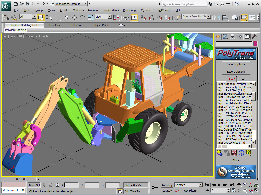
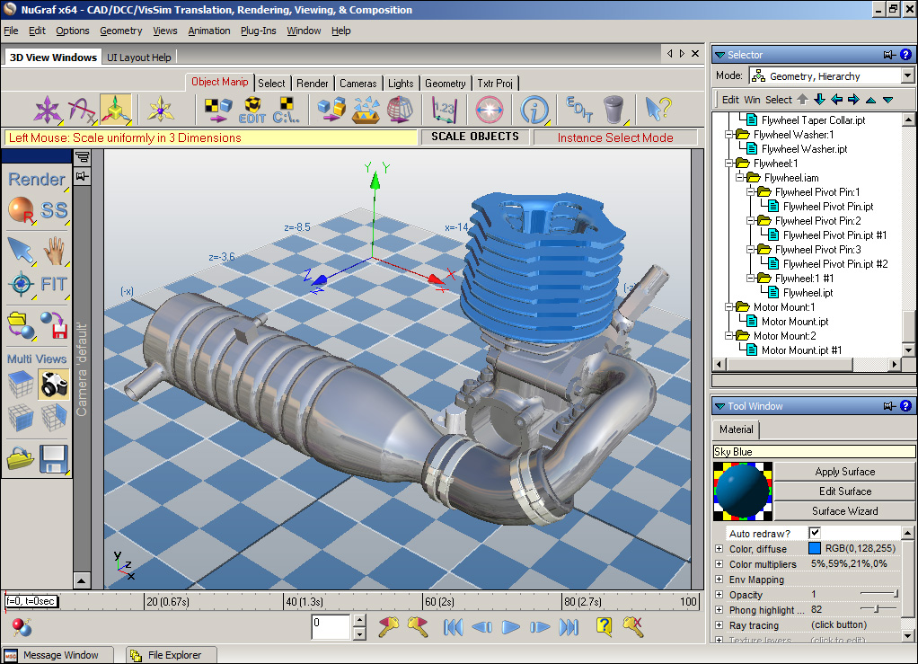
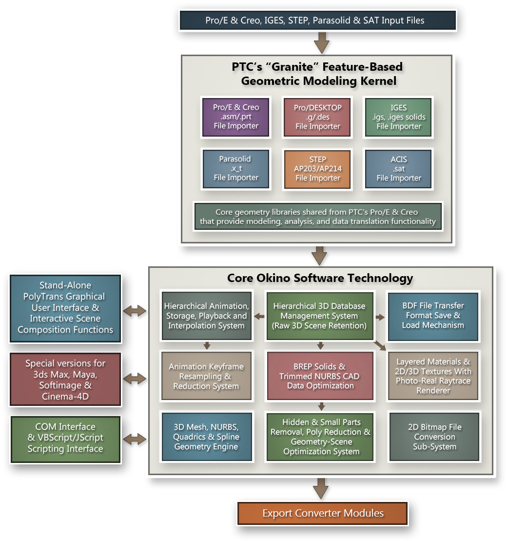
Okino has had one of the most extensively developed plug-in development systems and APIs since its original creation in 1988. Okino's plug-in development program allows third party developers and vendors to create new importers and exporters, as well as system-level plug-ins to create such add-in components as renderers, modelers and search engines.
Click on the following logo to jump to the online list of third party commercial plug-in modules available for Okino software.